
Ford Fusion: Body and Paint / Body Closures
- Front Door Alignment. General Procedures
- Hood Alignment. General Procedures
- Luggage Compartment Lid Alignment. General Procedures
- Rear Door Alignment. General Procedures
- Fuel Filler Door. Removal and Installation
- Fuel Filler Door Assembly. Removal and Installation
- Front Door Check Arm. Removal and Installation
- Rear Door Check Arm. Removal and Installation
- Front Door. Removal and Installation
- Fuel Filler Door Spring. Removal and Installation
- Rear Door. Removal and Installation
- Luggage Compartment Lid. Removal and Installation
- Luggage Compartment Lid Hinge. Removal and Installation
- Rear Door Check Arm. Removal and Installation
 Radiator Grille Opening Panel Reinforcement. Removal and Installation
Removal
NOTE:
Left hand (LH) side shown, right hand (RH) side similar.
NOTE:
Engine removed for clarity.
Overview
Remove the hood and prop rod...
 Front Door Alignment. General Procedures
Adjustment
NOTE:
Removal steps in this procedure may contain installation details.
NOTE:
LH shown, RH similar.
All alignments
Check the body to front door dimensions...
Other information:
Ford Fusion 2013–2020 Service Manual: Hood Alignment. General Procedures
Adjustment NOTE: Removal steps in this procedure may contain installation details. All alignments Inspect the hood-to-body dimensions. Refer to: Body and Frame (501-26 Body Repairs - Vehicle Specific Information and Tolerance Checks, Description and Operation)...
Ford Fusion 2013–2020 Service Manual: Camshaft Position (CMP) Sensor RH. Removal and Installation
Removal NOTE: Removal steps in this procedure may contain installation details. Remove the engine appearance cover. Disconnect the CMP sensor electrical connector, remove the retainer and the CMP sensor. Torque: 80 lb...
Categories
- Manuals Home
- 2nd Generation Ford Fusion Owners Manual
- 2nd Generation Ford Fusion Service Manual
- Electronic Parking Brake (EPB) Service Mode Activation and Deactivation. General Procedures
- Engine - 1.5L EcoBoost (118kW/160PS) – I4
- Memory Function
- New on site
- Most important about car
Manual Climate Control
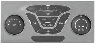
Note: Depending on your vehicle option package, the controls may look different from what you see here.

Copyright © 2026 www.fofusion2.com