Ford Fusion: Engine - 1.5L EcoBoost (118kW/160PS) – I4 / Intake Manifold. Removal and Installation
Special Tool(s) /
General Equipment
| Hose Clamp Remover/Installer |
Materials
| Name |
Specification |
Motorcraft® Threadlock 262
TA-26 |
WSK-M2G351-A6
|
Removal
-
Disconnect the battery ground cable.
Refer to: Battery Disconnect and Connect (414-01 Battery, Mounting and Cables, General Procedures).
-
Remove the following items:
-
Remove the air cleaner.
Refer to: Air Cleaner (303-12A Intake Air Distribution and Filtering - 1.5L EcoBoost (118kW/160PS) – I4, Removal and Installation).
-
Remove the upper air cleaner outlet pipe.
Refer to: Air Cleaner Outlet Pipe (303-12A Intake Air Distribution and Filtering - 1.5L EcoBoost (118kW/160PS) – I4, Removal and Installation).
-
Remove the EVAP canister purge valve.
Refer to: Evaporative Emission Canister Purge Valve (303-13A Evaporative Emissions - 1.5L EcoBoost (118kW/160PS) – I4, Removal and Installation).
-
Remove the charge air cooler.
Refer to: Charge Air Cooler (CAC) (303-12A Intake Air Distribution and Filtering - 1.5L EcoBoost (118kW/160PS) – I4, Removal and Installation).
-
Remove the generator.
Refer to: Generator - 1.5L EcoBoost (118kW/160PS) – I4 (414-02 Generator and Regulator, Removal and Installation).
-
-
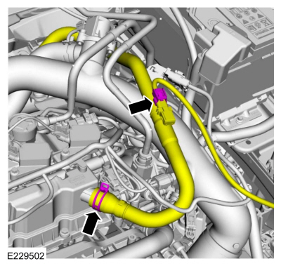
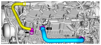
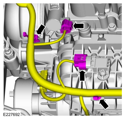
Disconnect the crankcase pressure sensor wiring harness electrical connector.
-
Release the clamps and position the crankcase vent tube aside.
Use the General Equipment: Hose Clamp Remover/Installer
-
Disconnect the wiring harness electrical connectors and retainer.
-
-
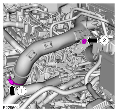
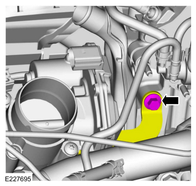
Loosen the CAC intake pipe clamp.
-
Remove the CAC intake pipe bolt.
-
Position the CAC intake pipe off the throttle body.
-
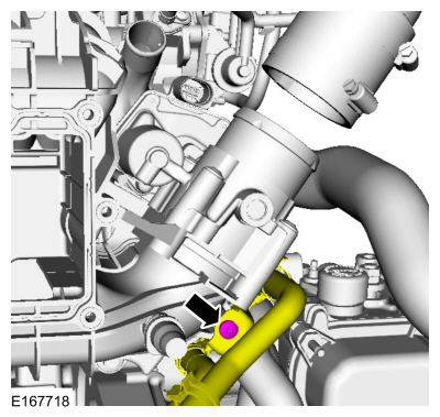
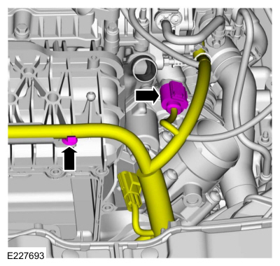
-
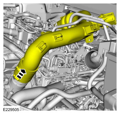
Disconnect and position the vent tube aside.
-
Release the clamps and remove the hose.
Use the General Equipment: Hose Clamp Remover/Installer
-
-
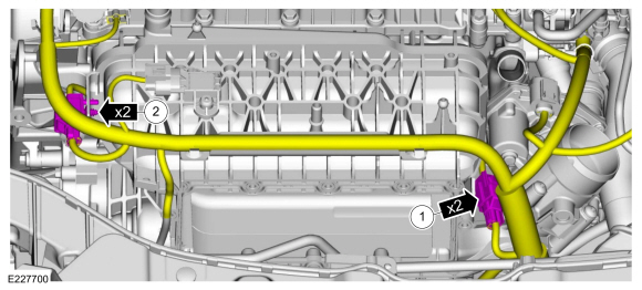
Detach the (KS) knock sensors.
-
Disconnect the (KS) knock sensors.
-
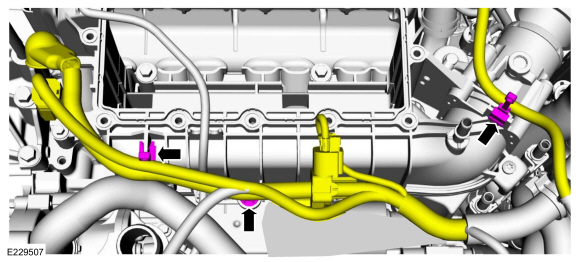
Disconnect the electrical connectors and the wiring harness retainers.
-
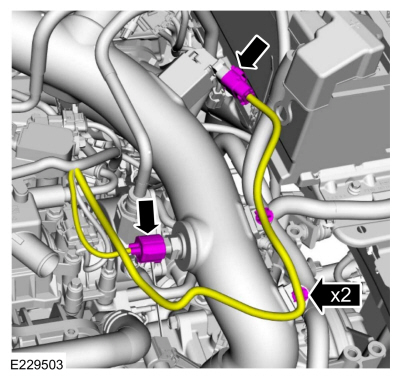
Disconnect the throttle body electrical connector and the wiring harness retainer.
-
Detach the wiring harness retainers and position the wire harness aside.
-
Remove the intake manifold support bracket bolt.
-
Remove the retainer and position the vacuum tube aside.
-
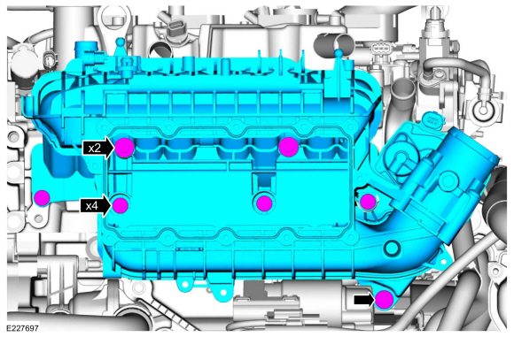
NOTE:
The bolts remain captured in the intake manifold.
Loosen the bolts and remove the intake manifold.
Installation
NOTICE:
If the engine is repaired or replaced because of upper
engine failure, typically including valve or piston damage, check the
intake manifold for metal debris. If metal debris is found, install a
new intake manifold. Failure to follow these instructions can result in
engine damage.
-
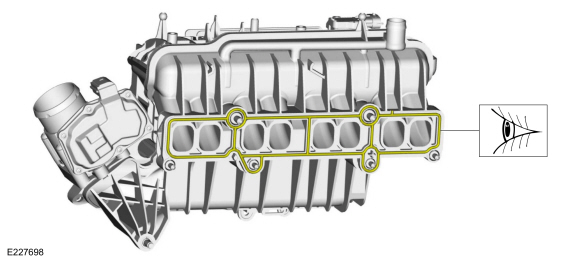
Visually inspect the intake manifold gasket for nicks,
cuts and abrasions. If these conditions are not present, the gaskets may
be re-used.
-
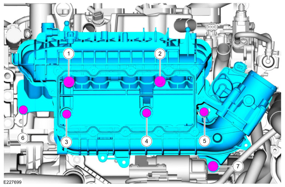
NOTE:
Apply threadlock 262 to the intake manifold bolt threads.
NOTE:
Make sure the KS wiring connectors are properly routed and not trapped behind the intake manifold while installing the intake manifold.
Install the intake manifold and tighten the bolts in sequence shown.
Material: Motorcraft® Threadlock 262
/ TA-26
(WSK-M2G351-A6)
Torque:
Stage 1:
Tighten bolts 1, 2 and 7 to:
18 lb.in (2 Nm)
Stage 2:
Tighten bolts 3 and 4 to:
18 lb.in (2 Nm)
Stage 3:
Tighten bolts 1 and 2 to:
159 lb.in (18 Nm)
Stage 4:
Tighten bolts 3, 4, 5 and 6 to:
89 lb.in (10 Nm)
Stage 5:
Retighten bolts 1 and 2 to:
159 lb.in (18 Nm)
Stage 6:
Tighten bolt 7 to:
159 lb.in (18 Nm)
Stage 7:
Retighten bolts 3, 4, 5 and 6 to:
89 lb.in (10 Nm)
-
Position the vacuum tube and install the retainer.
Torque:
89 lb.in (10 Nm)
-
Install the intake manifold support bracket bolt.
Torque:
159 lb.in (18 Nm)
-
Position the wire harness and attach the wiring harness retainers.
-
Connect the throttle body electrical connector and the wiring harness retainer.
-
Connect the electrical connectors and the wiring harness retainers.
-
-
Connect the (KS) knock sensors.
-
Attach the (KS) knock sensors.
-
-
Install the hose.
Use the General Equipment: Hose Clamp Remover/Installer
-
Install the CAC intake pipe on the throttle body.
-
-
Tighten the CAC intake pipe clamp.
Torque:
44 lb.in (5 Nm)
-
Install the CAC intake pipe bolt.
Torque:
71 lb.in (8 Nm)
-
Connect the wiring harness electrical connectors and retainer.
-
-
Position the crankcase vent tube and release clamp.
Use the General Equipment: Hose Clamp Remover/Installer
-
Connect the crankcase pressure sensor wiring harness electrical connector.
 |
|
-
Install the following items:
-
Install the generator.
Refer to: Generator - 1.5L EcoBoost (118kW/160PS) – I4 (414-02 Generator and Regulator, Removal and Installation).
-
Install the charge air cooler.
Refer to: Charge Air Cooler (CAC) (303-12A Intake Air Distribution and Filtering - 1.5L EcoBoost (118kW/160PS) – I4, Removal and Installation).
-
Install the EVAP canister purge valve.
Refer to: Evaporative Emission Canister Purge Valve (303-13A Evaporative Emissions - 1.5L EcoBoost (118kW/160PS) – I4, Removal and Installation).
-
Install the upper air cleaner outlet pipe.
Refer to: Air Cleaner Outlet Pipe (303-12A Intake Air Distribution and Filtering - 1.5L EcoBoost (118kW/160PS) – I4, Removal and Installation).
-
Install the air cleaner.
Refer to: Air Cleaner (303-12A Intake Air Distribution and Filtering - 1.5L EcoBoost (118kW/160PS) – I4, Removal and Installation).
-
Connect the battery ground cable.
Refer to: Battery Disconnect and Connect (414-01 Battery, Mounting and Cables, General Procedures).
Special Tool(s) /
General Equipment
303-103
(T74P-6375-A)
Holding Tool, FlywheelT74P-77000-ATKIT-2009TC-F
Removal
Remove the transmission...
Special Tool(s) /
General Equipment
Strap Wrench
Oil Drain Equipment
Locking Pliers
Materials
Name
Specification
Engine Oil - SAE 5W-20 - Synthetic Blend Motor OilXO-5W20-Q1SP
WSS-M2C945-B1
Motorcraft® Orange Prediluted Antifreeze/CoolantVC-3DIL-B
WSS-M97B44-D2
Motorcraft® Orange Concentrated Antifreeze/CoolantVC-3-B
WSS-M97B44-D
..
Other information:
Removal
With the vehicle in NEUTRAL, position it on a hoist.
Refer to: Jacking and Lifting - Overview (100-02 Jacking and Lifting, Description and Operation).
Remove the retainers and the engine front undershield.
Remove the retainers and the engine undershield.
Remove the bolts, remove the roll restrictor an..
Special Tool(s) /
General Equipment
303-1556Locking Tool, Timing BeltTKIT-2010B-FLMTKIT-2010B-ROW
303-748Locking Tool, CrankshaftTKIT-2010B-FLMTKIT-2010B-ROW
Hose Clamp Remover/Installer
4 mm Drill Bit
Removal
NOTE:
The original coolant pump may not be equipped with a clutch and wiring harness connector.
Refer to: Engine Cooling System Health and Safet..


 Flexplate. Removal and Installation
 Oil Cooler. Removal and Installation