Ford Fusion: Engine - 1.5L EcoBoost (118kW/160PS) – I4 / Flexplate. Removal and Installation
Ford Fusion 2013–2020 Service Manual / Powertrain / Engine / Engine - 1.5L EcoBoost (118kW/160PS) – I4 / Flexplate. Removal and Installation
Special Tool(s) / General Equipment
 |
303-103
(T74P-6375-A)
Holding Tool, Flywheel T74P-77000-A TKIT-2009TC-F |
Removal
-
Remove the transmission.
Refer to: Transmission - 1.5L EcoBoost (118kW/160PS) – I4 (307-01A Automatic Transmission - 6-Speed Automatic Transmission – 6F35, Removal and Installation).
-
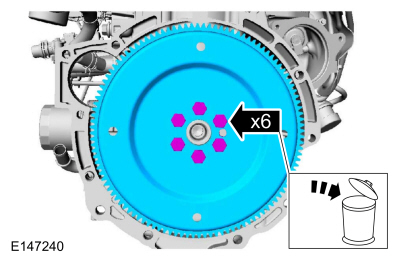
Remove the bolts and the flexplate. Discard the bolts.
 |
Installation
-
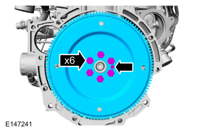
NOTE: Only tighten the bolts finge-rtight at this stage.
Install the flexplate and the bolts finger-tight.
 |
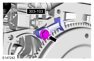
- Install Special Service Tool: 303-103 (T74P-6375-A) Holding Tool, Flywheel.
 |
-
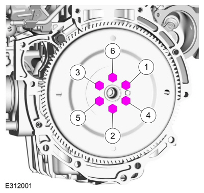
Tighten the flexplate bolts in sequence shown in 4 stages.
Torque:
Stage 1: 133 lb.in (15 Nm)
Stage 2: 18 lb.ft (25 Nm)
Stage 3: 22 lb.ft (30 Nm)
Stage 4: 90°
 |
- Remove Special Service Tool: 303-103 (T74P-6375-A) Holding Tool, Flywheel.
 |
-
Install the transmission.
Refer to: Transmission - 1.5L EcoBoost (118kW/160PS) – I4 (307-01A Automatic Transmission - 6-Speed Automatic Transmission – 6F35, Removal and Installation).
-
After completing the repairs, perform the Misfire Monitor Neutral Profile Correction procedure.
 Engine Mount. Removal and Installation
Special Tool(s) /
General Equipment
Trolley Jack
Wooden Block
Removal
With the vehicle in NEUTRAL, position it on a hoist.
Refer to: Jacking and Lifting - Overview (100-02 Jacking and Lifting, Description and Operation)...
 Intake Manifold. Removal and Installation
Special Tool(s) /
General Equipment
Hose Clamp Remover/Installer
Materials
Name
Specification
Motorcraft® Threadlock 262TA-26
WSK-M2G351-A6
Removal
Disconnect the battery ground cable...
Other information:
Ford Fusion 2013–2020 Owners Manual: Information Display Controls (Type 1 and Type 2)
Press the up or down arrow buttons to scroll through the list. Press the right arrow button to enter a sub-menu. Press the left arrow button to exit a menu. Press and hold the left arrow button at any time to return to the main menu display (escape button)...
Ford Fusion 2013–2020 Service Manual: Axle Assembly. Removal and Installation
Special Tool(s) / General Equipment Transmission Jack Materials Name Specification Motorcraft® SAE 80W-90 Premium Rear Axle LubricantXY-80W90-QL WSP-M2C197-A Removal Remove the rear halfshafts. Refer to: Rear Halfshaft (205-05 Rear Drive Halfshafts, Removal and Installation)...
Categories
- Manuals Home
- 2nd Generation Ford Fusion Owners Manual
- 2nd Generation Ford Fusion Service Manual
- Pre-Collision Assist (IF EQUIPPED)
- Memory Function
- Engine
- New on site
- Most important about car
Using Seatbelts During Pregnancy
WARNING: Always ride and drive with your seatback upright and properly fasten your seatbelt. Fit the lap portion of the seatbelt snugly and low across the hips. Position the shoulder portion of the seatbelt across your chest. Pregnant women must follow this practice. See the following figure.

Copyright © 2026 www.fofusion2.com