Ford Fusion: Automatic Transmission - 6-Speed Automatic Transmission – 6F35 / Transmission Fluid Auxiliary Pump. Removal and Installation
Ford Fusion 2013–2020 Service Manual / Powertrain / Automatic Transmission / Automatic Transmission - 6-Speed Automatic Transmission – 6F35 / Transmission Fluid Auxiliary Pump. Removal and Installation
Removal
-
With the vehicle in NEUTRAL, position it on a hoist.
Refer to: Jacking and Lifting - Overview (100-02 Jacking and Lifting, Description and Operation).
Refer to: Engine Front Undershield (501-02 Front End Body Panels, Removal and Installation).
-
Remove the LH front wheel and tire.
Refer to: Wheel and Tire (204-04A Wheels and Tires, Removal and Installation).
-
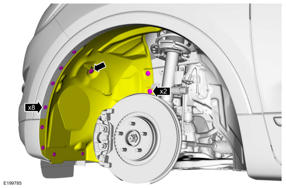
Remove the retainers and position the LH fender splash shield aside.
 |
-
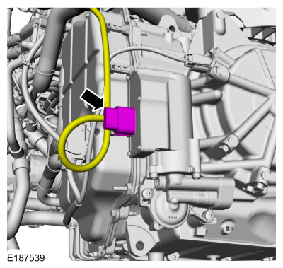
Disconnect the transmission fluid auxiliary pump electrical connector.
 |
-
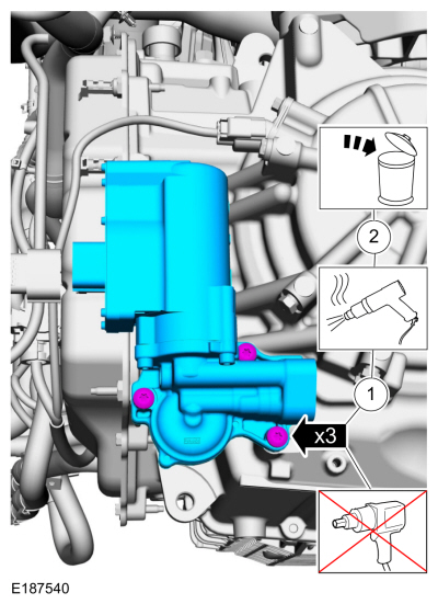
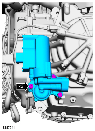
NOTICE: Do not use power tools to remove the transmission fluid auxiliary pump bolts or damage can occur.
Remove the bolts and the transmission fluid auxiliary pump.
-
Apply heat to the bolts to soften the Loctite®.
-
Remove and discard the bolts.
-
Apply heat to the bolts to soften the Loctite®.
 |
-
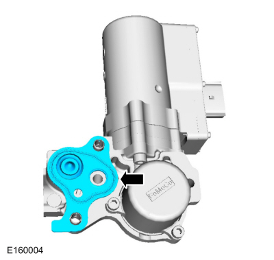
Remove the transmission fluid auxiliary pump gasket.
 |
-
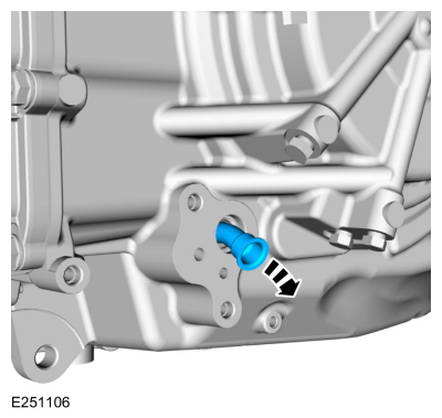
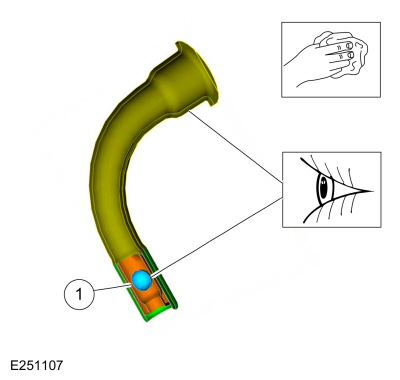
Remove the transmission fluid auxiliary pump supply tube assembly.
 |
-
Clean and inspect the transmission fluid auxiliary pump supply tube and check ball.
-
Check ball (part of the transmission fluid auxiliary pump supply tube)
-
Check ball (part of the transmission fluid auxiliary pump supply tube)
 |
Installation
-
Install the transmission fluid auxiliary pump supply tube assembly.
 |
-
Install the transmission fluid auxiliary pump gasket.
 |
-
Install the transmission fluid auxiliary pump and the new bolts.
Torque: 115 lb.in (13 Nm)
 |
-
Connect the transmission fluid auxiliary pump electrical connector.
 |
-
NOTE: TFT must be greater than 38ºC (100ºF) for the PCM to command the pump on.
Using the scan tool verify the TFT is above 38ºC (100ºF).
-
If TFT is below 38ºC (100ºF), run engine at 3000 RPM until specified temperature is achieved (approximately 2-4 minutes).
-
If TFT is below 38ºC (100ºF), run engine at 3000 RPM until specified temperature is achieved (approximately 2-4 minutes).
-
Prime the Transmission Fluid Auxiliary Pump.
-
Key ON, Engine OFF.
-
Using the scan tool, command TRANS_PMP_CMD to 80%
for 30 seconds. If the pump cannot be commanded on, verify TFT is above 38ºC (100ºF).
-
Clear DTCs.
-
Key ON, Engine OFF.
-
Carry out a road test until there is a stop / start
event. If the restart is harsh, repeat the Transmission Fluid Pump prime
procedure.
-
Continue road test and evaluate each stop / start event.
Repeat prime procedure until three consecutive normal stop / start
events are achieved.
-
Check the transmission fluid level.
Refer to: Transmission Fluid Level Check (307-01A Automatic Transmission - 6-Speed Automatic Transmission – 6F35, General Procedures).
 Transmission Case Bushing. Removal and Installation
Removal
To remove the LH halfshaft bushing, transmission disassembly is required.
Refer to: Transmission (307-01A Automatic Transmission - 6-Speed Automatic Transmission – 6F35, Overhaul)...
 Transmission Internal Wiring Harness Frame. Removal and Installation
Special Tool(s) /
General Equipment
307-636Alignment Pins- Valve BodyTKIT-2008ET-FLMTKIT-2008ET-ROW
Removal
Remove the main control cover...
Other information:
Ford Fusion 2013–2020 Service Manual: Steering Column. Diagnosis and Testing
DTC Charts Diagnostics in this manual assume a certain skill level and knowledge of Ford-specific diagnostic practices. REFER to: Diagnostic Methods (100-00 General Information, Description and Operation). SCCM DTC Chart DTC Description Action B1298:09 Steering Column Adjust Up Switch: Component Failure INSTAL..
Ford Fusion 2013–2020 Service Manual: Front Side Member and Fender Apron Panel LH. Removal and Installation
Special Tool(s) / General Equipment Resistance Spotwelding Equipment Hot Air Gun Air Body Saw 8 mm Drill Bit MIG/MAG Welding Equipment Spot Weld Drill Bit Materials Name Specification Metal Bonding AdhesiveTA-1, TA-1-B, 3M™ 08115, LORD Fusor® 108B - Seam SealerTA-2-B, 3M™ 08308, LORD Fusor® 803DTM - Removal &nbs..
Categories
- Manuals Home
- 2nd Generation Ford Fusion Owners Manual
- 2nd Generation Ford Fusion Service Manual
- Pre-Collision Assist (IF EQUIPPED)
- Memory Function
- Under Hood Overview - 1.5L EcoBoost™, 2.0L EcoBoost™, 2.5L, 2.7L EcoBoost™
- New on site
- Most important about car
Using Seatbelts During Pregnancy
WARNING: Always ride and drive with your seatback upright and properly fasten your seatbelt. Fit the lap portion of the seatbelt snugly and low across the hips. Position the shoulder portion of the seatbelt across your chest. Pregnant women must follow this practice. See the following figure.

Copyright © 2026 www.fofusion2.com