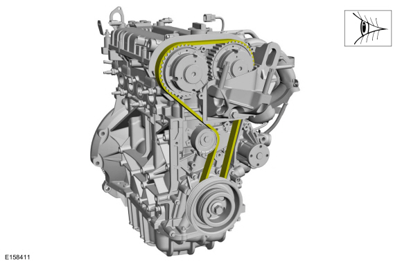
Ford Fusion: Engine - 1.5L EcoBoost (118kW/160PS) – I4 / Cylinder Head. Removal and Installation
Special Tool(s) /
General Equipment
 |
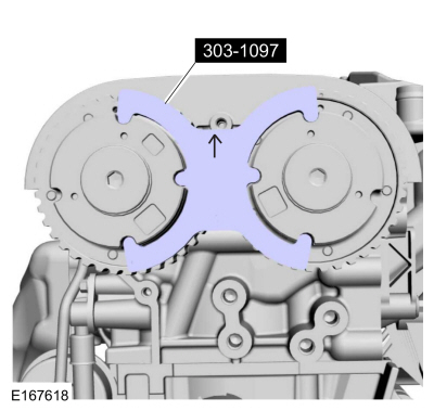
303-1097
Locking Tool, Variable Camshaft Timing Oil Control Unit
TKIT-2010B-FLM
TKIT-2010B-ROW |
 |
303-1556
Locking Tool, Timing Belt
TKIT-2010B-FLM
TKIT-2010B-ROW |
 |
303-748
Locking Tool, Crankshaft
TKIT-2010B-FLM
TKIT-2010B-ROW |
| Strap Wrench |
| Oil Drain Equipment |
| Hot Air Gun |
| Hose Clamp Remover/Installer |
Materials
| Name |
Specification |
Flange Sealant
CU7Z-19B508-A |
WSS-M2G348-A11
|
Motorcraft® Metal Surface Prep Wipes
ZC-31-B |
-
|
Engine Oil - SAE 5W-20 - Synthetic Blend Motor Oil
XO-5W20-Q1SP |
WSS-M2C945-B1
|
Motorcraft® Orange Concentrated Antifreeze/Coolant
VC-3-B |
WSS-M97B44-D
|
Removal
-
With the vehicle in NEUTRAL, position it on a hoist.
Refer to: Jacking and Lifting - Overview (100-02 Jacking and Lifting, Description and Operation).
-
Release the fuel system pressure.
Refer to: Fuel System Pressure Release (310-00A Fuel System - General Information - 1.5L EcoBoost (118kW/160PS) – I4, General Procedures).
-
Disconnect the battery ground cable.
Refer to: Battery Disconnect and Connect (414-01 Battery, Mounting and Cables, General Procedures).
-
Remove the following items:
-
Remove the CAC intake pipe.
Refer to: Charge Air Cooler (CAC) Intake Pipe (303-12A Intake Air Distribution and Filtering - 1.5L EcoBoost (118kW/160PS) – I4, Removal and Installation).
-
Remove the EVAP canister purge valve.
Refer to: Evaporative Emission Canister Purge Valve (303-13A Evaporative Emissions - 1.5L EcoBoost (118kW/160PS) – I4, Removal and Installation).
-
Drain the cooling system.
Refer to: Engine Cooling System Draining, Vacuum Filling and Bleeding (303-03A Engine Cooling - 1.5L EcoBoost (118kW/160PS) – I4, General Procedures).
-
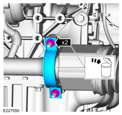
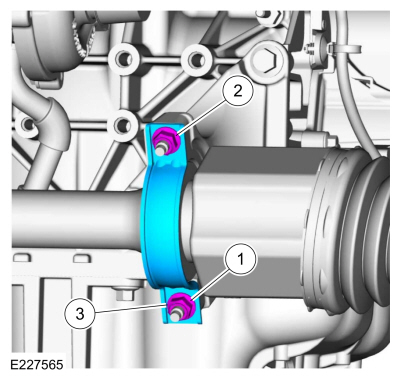
Remove and discard the halfshaft bearing retaining nuts and strap.
-
NOTE:
It may be necessary to rotate the halfshaft to remove the front lower bolt.
Remove the bolts and position the halfshaft bearing bracket aside.
-
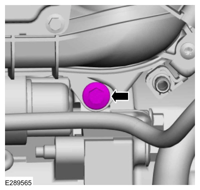
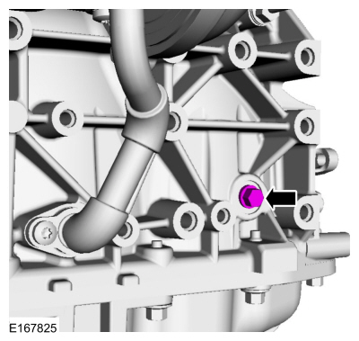
Remove the engine plug bolt.
-
Loosen the coolant pump pulley bolts.
-
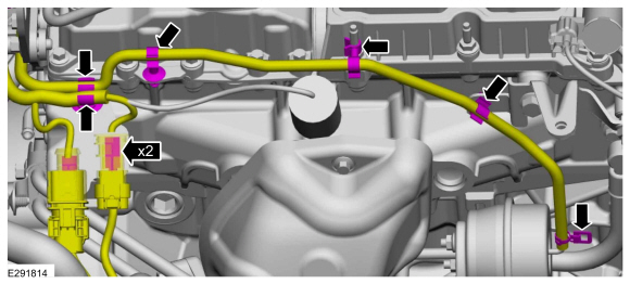
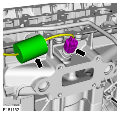
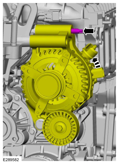
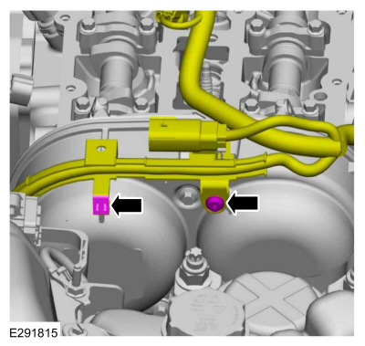
Disconnect the CKP sensor electrical connector and wire harness retainers.
-
If equipped, remove the retainers and the heat shield.
-
-
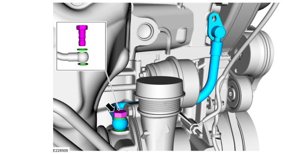
Disconnect the turbocharger hose and the retainers.
Use the General Equipment: Hose Clamp Remover/Installer
-
Disconnect the electrical connectors from the bracket.
-
Disconnect the CHT sensor electrical connector.
-
Remove the following items:
-
Remove the High-Pressure fuel pump drive unit.
Refer to: High-Pressure Fuel Pump Drive Unit (303-04A Fuel Charging and Controls - 1.5L EcoBoost (118kW/160PS) – I4, Removal and Installation).
-
Remove the brake vacuum pump.
Refer to: Brake Vacuum Pump - 1.5L EcoBoost (118kW/160PS) – I4 (206-07 Power Brake Actuation, Removal and Installation).
-
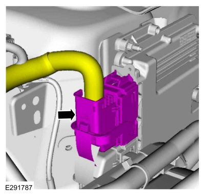
Disconnect the PCM electrical connector.
-
Detach the wiring harness retainer, disconnect the electrical connector and position the wiring harness aside.
-
Remove the wiring harness bolt. Detach the wire harness retainer and position the wire harness aside.
-
Disconnect the IAT sensor electrical connector and the wire harness retainer.
-
-
Disconnect and position aside the coolant tube.
-
Detach and disconnect the KS electrical connector.
-
Detach and disconnect the KS electrical connector.
-
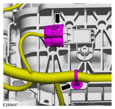
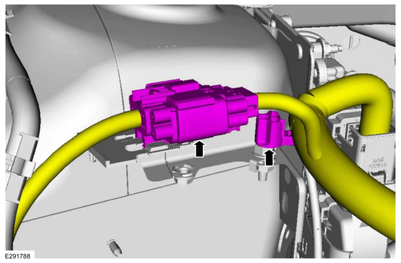
Disconnect the TB (throttle body) electrical connector and the wire harness retainer.
-
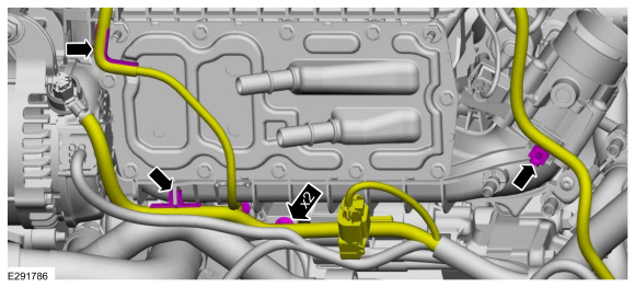
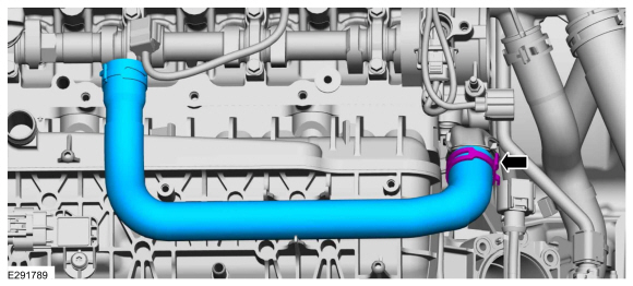
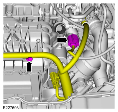
Disconnect the quick release couplings and position the coolant hoses aside.
-
Disconnect the wire harness retainers.
-
Disconnect the retainer from the coolant tube bracket.
-
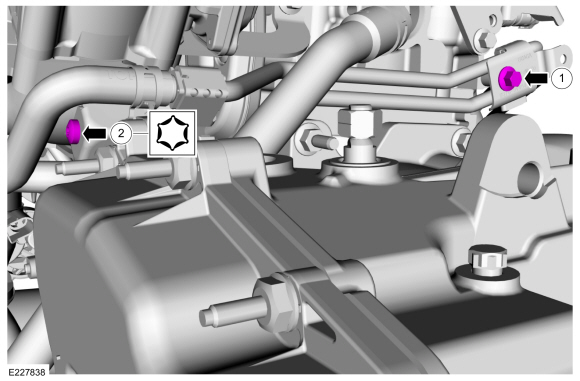
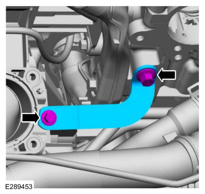
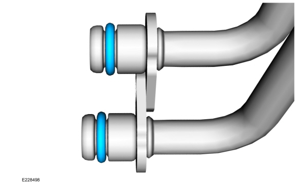
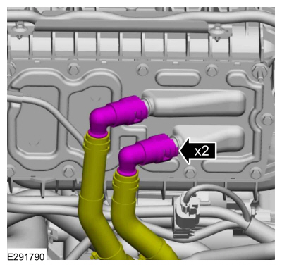
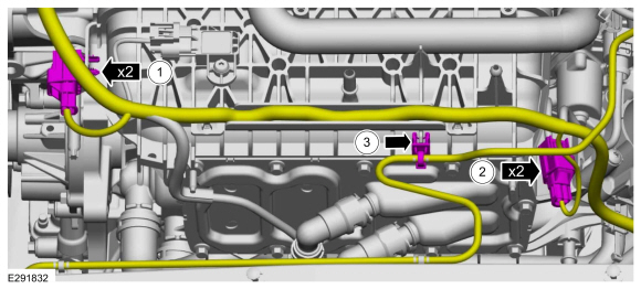
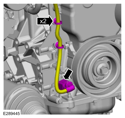
Remove the retainers for the turbocharger coolant tubes.
-
Remove the bolt and position aside the turbocharger cooling tubes.
-
Remove and discard the turbocharger coolant tube O-ring seals.
-
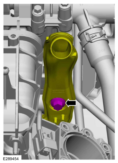
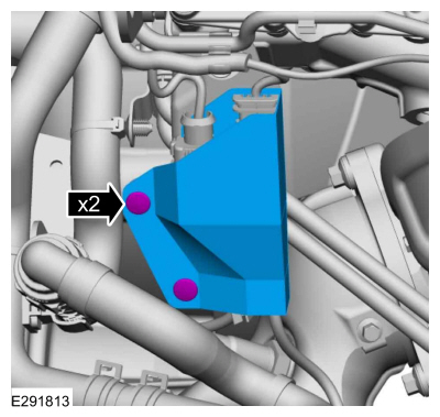
Remove the bolts and turbocharger heat shield.
-
Remove the TC oil supply tube bolt and disconnect from the engine.
-
Remove and discard the TC oil supply tube assembly.
-
NOTE:
The turbocharger is left in place during the cylinder head procedure.
Remove and discard the TC nuts.
-
Remove and discard the TC mounting studs and the gasket.
-
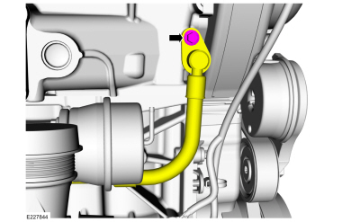
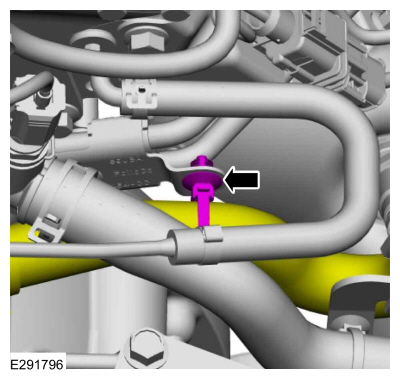
Disconnect the coolant hose and position aside.
Use the General Equipment: Hose Clamp Remover/Installer
-
-
Remove the nut.
-
Remove the stud and position out the coolant outlet.
-
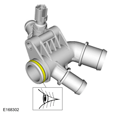
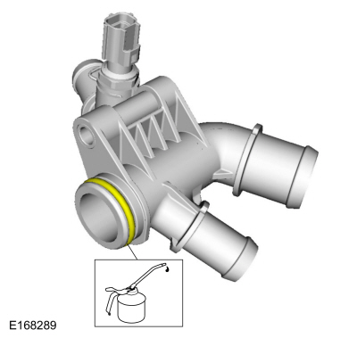
Inspect the coolant outlet O-ring seal and replace if damaged.
-
Remove the TB (throttle body).
Refer to: Throttle Body (303-04A Fuel Charging and Controls - 1.5L EcoBoost (118kW/160PS) – I4, Removal and Installation).
-
Remove the bolts and the intake manifold bracket.
-
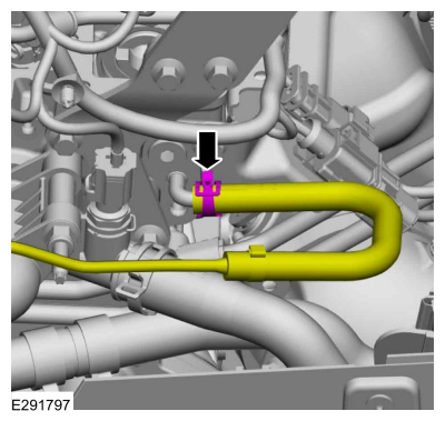
Disconnect and remove the engine vent hose.
Use the General Equipment: Hose Clamp Remover/Installer
-
NOTE:
The bolt is captured in the oil separator tube.
Loosen the bolt for the oil separator tube.
-
NOTE:
The bolt is captured in the intake manifold.
-
Loosen the bolt for the intake manifold.
-
Using a tie strap or rubber band, secure the intake manifold bolt in the removed position.
-
Remove the following items:
-
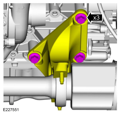
Remove the engine mount.
Refer to: Engine Mount (303-01A Engine - 1.5L EcoBoost (118kW/160PS) – I4, Removal and Installation).
-
Remove the accessory drive belt.
Refer to: Accessory Drive Belt (303-05A Accessory Drive - 1.5L EcoBoost (118kW/160PS) – I4, Removal and Installation).
-
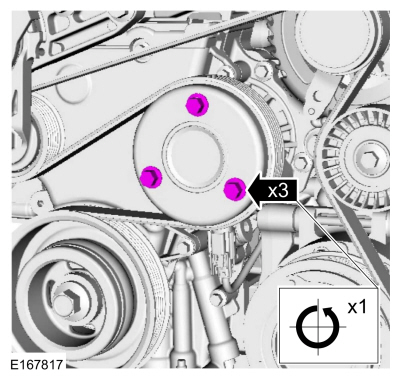
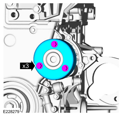
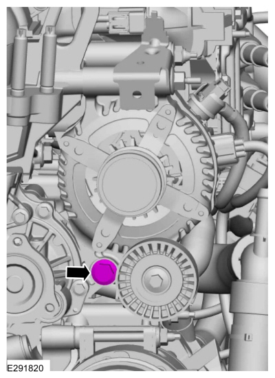
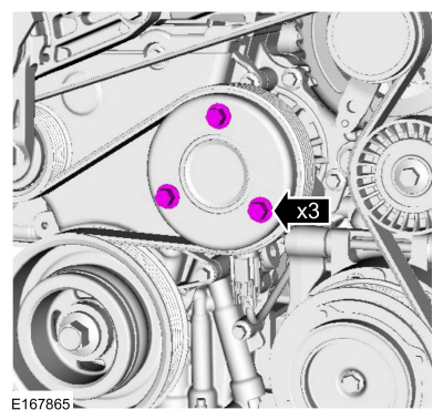
Remove the bolts and the coolant pump pulley.
-
-
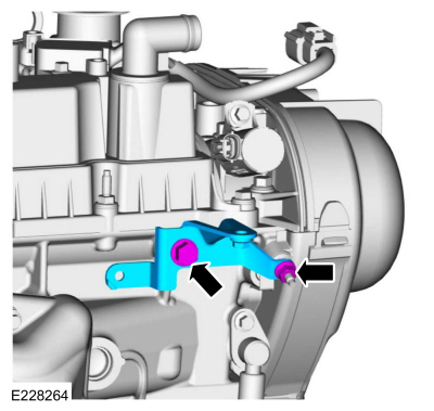
Remove the upper generator mounting stud bolt and if equipped, the bracket.
-
Remove the generator mounting nut.
-
Remove the generator stud.
-
Loosen the bolt and position out the generator.
-
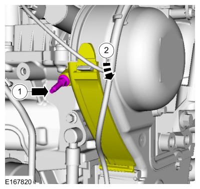
Remove the engine mount stud.
-
Remove the nut, the bolt and the bracket.
-
-
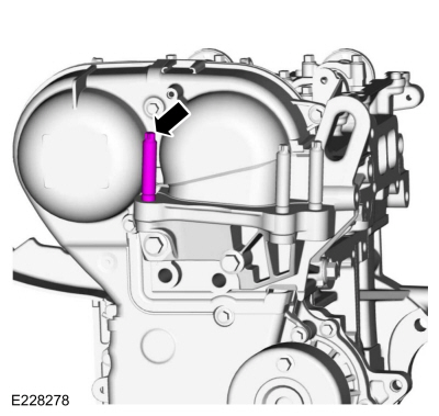
Remove the timing cover stud bolt.
-
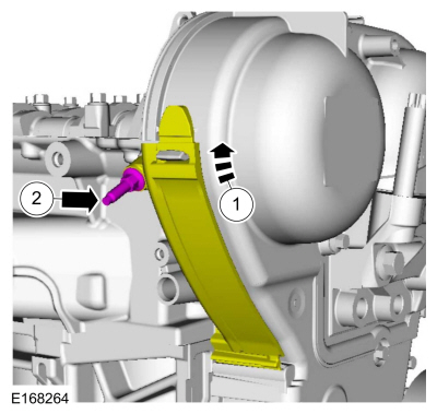
Detach the cover from the retainer and open.
-
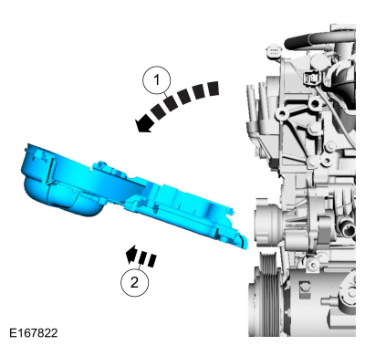
Remove the engine front cover bolts.
-
Remove the engine front cover.
-
NOTE:
Timing belt removal is only necessary if a new timing belt is being installed.
Install a new timing belt if the existing belt is contaminated by coolant or oil.
Refer to: Timing Belt (303-01A Engine - 1.5L EcoBoost (118kW/160PS) – I4, Removal and Installation).
-
NOTE:
Note the different lengths of the bolts for installation.
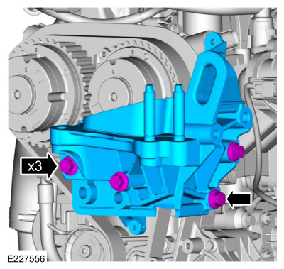
Remove the bolts and the engine mount bracket.
-
NOTE:
Only rotate the crankshaft in a clockwise direction.
Rotate the crankshaft slowly until the 11 o'clock position.
-
NOTE:
The Crankshaft TDC Timing Pin will contact the
crankshaft and prevent it from turning past TDC. However, the crankshaft
can still be rotated in the counterclockwise direction. The crankshaft
must remain at the TDC position during the crankshaft pulley removal and
installation.
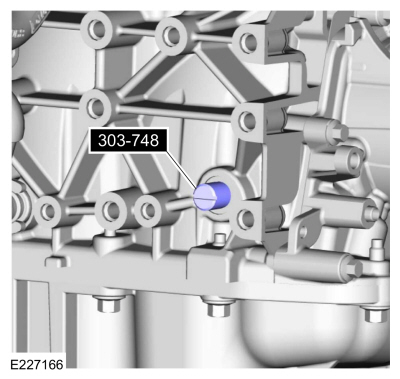
Install Special Service Tool: 303-748
Locking Tool, Crankshaft.
-
NOTE:
Only rotate the crankshaft in a clockwise direction.
Rotate the crankshaft slowly clockwise until the crankshaft balance weight is up against the Crankshaft TDC Timing Peg. The engine is now at TDC.
-
-
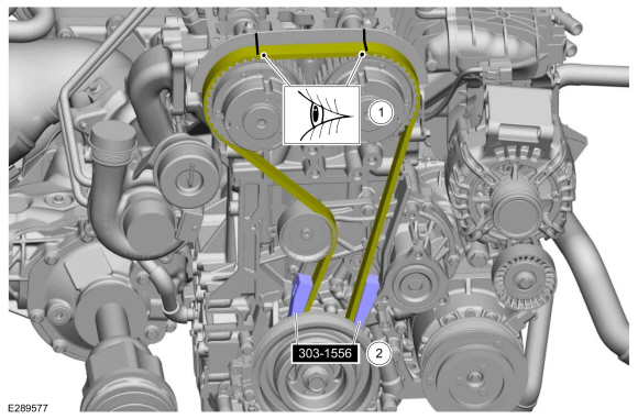
Install Special Service Tool: 303-1556
Locking Tool, Timing Belt.
-
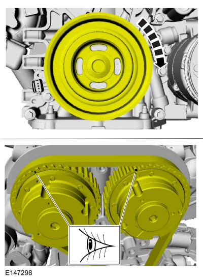
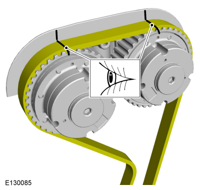
Mark the position of the components before removal.
-
NOTICE:
Do not rotate the crankshaft or camshafts while the timing belt is removed.
-
Rotate the timing belt tensioner.
-
General Equipment: Holding Pin
Install a holding pin.
-
Carefully remove the timing belt from the VCT units.
-
Remove the camshaft seals.
Refer to: Camshaft Seal (303-01A Engine - 1.5L EcoBoost (118kW/160PS) – I4, Removal and Installation).
-
NOTICE:
Use a heat gun to soften the flange sealant, this
will aid in the removal of the camshaft mega cap. Failure to follow
these directions may result in damage to the camshaft mega cap.
NOTICE:
Do not pry on camshafts when removing or damage to the camshafts may occur.
NOTE:
Note the location and orientation of each camshaft
bearing cap and the position of the camshaft lobes on the No. 1 cylinder
for installation reference.
NOTE:
Discard the 4 mega cap bolts and 8 of the camshaft
bearing cap bolts, 8 of the camshaft bearing cap bolts will be used to
hold camshafts and valve tappets in place and will be discarded later in
this procedue.
-
Remove the camshaft caps.
-
Heat and remove the mega cap.
Use the General Equipment: Hot Air Gun
-
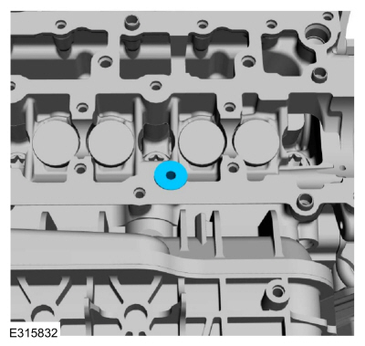
Remove the crankcase vent oil drain tube.
-
Inspect crankcase vent oil drain tube and replace if damaged.
-
Remove and discard the O-ring seal.
-
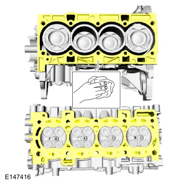
Make sure that the mating faces are clean and free of foreign material.
-
Make sure that the mating faces are clean and free of foreign material.
-
NOTE:
Make sure that the cylinder head is at ambient air temperature before removing the cylinder head bolts.
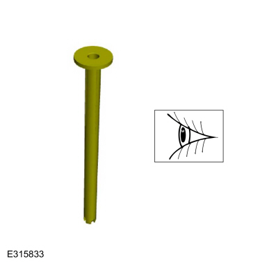
Remove and discard the cylinder head bolts.
-
NOTE:
If any new parts are being installed (cylinder head,
valves, tappets, camshafts) it is necessary to check the valve
clearance. If the original parts are being installed it is not necessary
to check the valve clearance.
NOTE:
The camshafts are installed to keep the valve tappets in place during cleaning.
Position the camshafts in the neutral position in the
cylinder head. Install the 4 camshaft caps and the 8 original bolts.
Tighten the camshaft bearing cap bolts 1 turn at a time until seated
against the cylinder head.
-
NOTE:
Note the routing of the KS (knock sensor) wiring before removal of the cylinder head.
Remove the cylinder head.
-
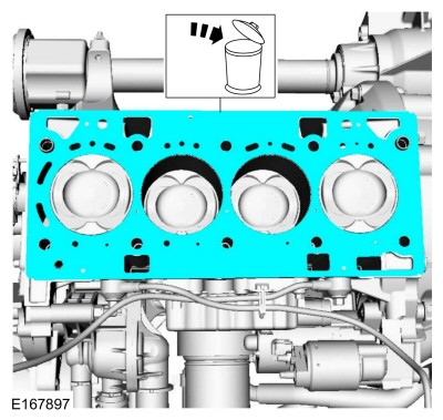
Remove and discard the cylinder head gasket.
-
NOTE:
Support the cylinder head on a bench with the head gasket side up.
Inspect the cylinder head and cylinder block distortion.
Refer to: Cylinder Head Distortion (303-00 Engine System - General Information, General Procedures).
Refer to: Cylinder Block Distortion (303-00 Engine System - General Information, General Procedures).
Installation
-
NOTE:
If any new parts are being installed (cylinder head,
valves, tappets, camshafts) it is necessary to check the valve
clearance. If the original parts are being installed it is not necessary
to check the valve clearance.
Refer to cylinder head.
Refer to: Cylinder Head (303-01A Engine - 1.5L EcoBoost (118kW/160PS) – I4, Disassembly and Assembly of Subassemblies).
-
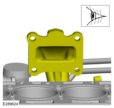
Clean and inspect the turbocharger mounting flange.
-
NOTICE:
Do not use metal scrapers, wire brushes, power
abrasive discs or other abrasive means to clean the sealing surfaces.
These tools cause scratches and gouges that make leak paths. Use a
plastic scraping tool to remove all traces of the head gasket.
NOTE:
If there is no residual gasket material present,
metal surface prep can be used to clean and prepare the surfaces.
Make sure that the mating faces are clean and free of foreign material.
Material: Motorcraft® Metal Surface Prep Wipes
/ ZC-31-B
-
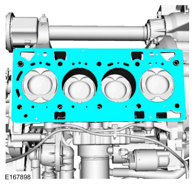
Install the cylinder head gasket.
-
NOTE:
Note the routing of the KS (knock sensor) wiring before installation of the cylinder head.
Install the cylinder head.
-
NOTICE:
Failure to follow the camshaft loosening procedure
can result in damage to the camshafts. Discard the camshaft bearing cap
bolts.
NOTE:
For cylinder heads with the camshafts partially installed.
NOTE:
Discard the 8 camshaft bearing cap bolts.
If necessary, loosen the camshaft bearing cap bolts 1
turn at a time until all tension is released from the camshaft bearing
caps. Remove the bolts, the camshaft caps and the camshafts. Discard the
camshaft bearing cap bolts.
-
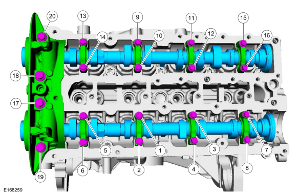
NOTE:
Make sure that new bolts are installed.
NOTE:
Make sure that no fluids are present in the cylinder head bolt threaded bores.
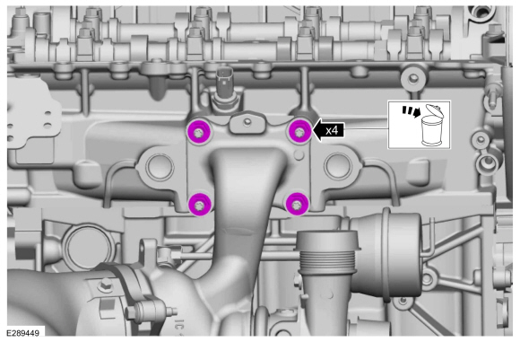
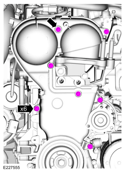
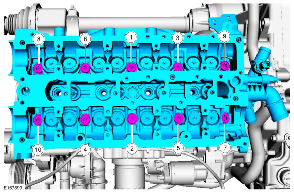
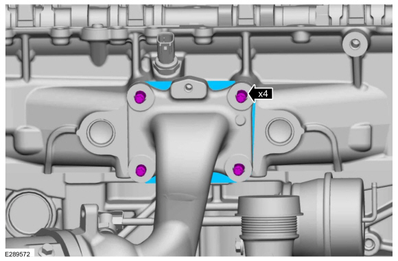
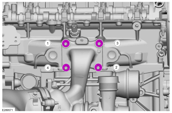
Install the new cylinder head bolts and tighten in sequence shown.
Torque:
Stage 1:
44 lb.in (5 Nm)
Stage 2:
133 lb.in (15 Nm)
Stage 3:
26 lb.ft (35 Nm)
Stage 4:
90°
Stage 5:
90°
-
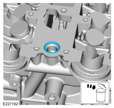
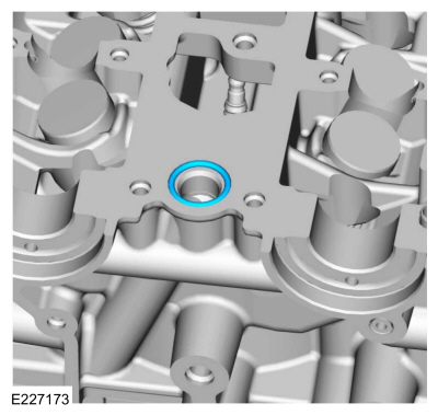
Install a new mega cap O-ring seal.
-
Install the crankcase vent oil drain tube.
-
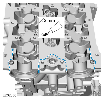
NOTE:
The VCT bridge must be installed within 5 minutes of applying the gasket maker.
Apply a 2 mm bead of flange sealant.
Material: Flange Sealant
/ CU7Z-19B508-A
(WSS-M2G348-A11)
 |
|
-
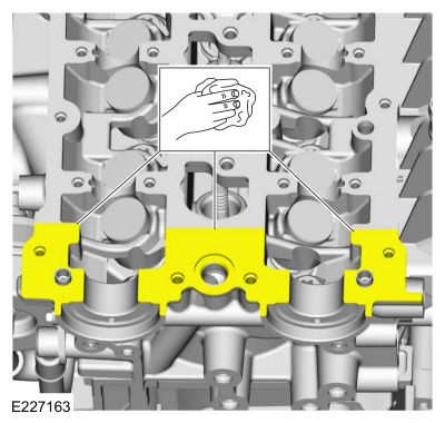
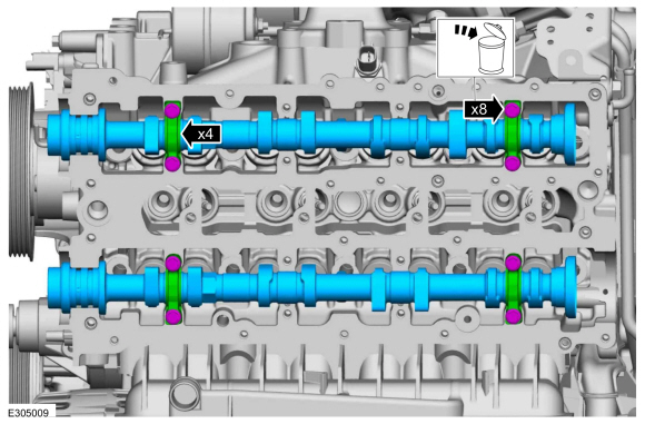
NOTICE:
Failure to follow the camshaft tightening procedure can result in damage to the camshafts.
NOTICE:
Make sure that the camshafts and camshaft bearing
caps are installed in their original locations or damage to the engine
may occur.
NOTE:
Make sure that the mating faces are clean and free of foreign material.
NOTE:
Apply clean engine oil to the bearing surfaces of the camshafts, camshaft bearing caps and the VCT bridge.
NOTE:
Make sure that new bolts are installed.
-
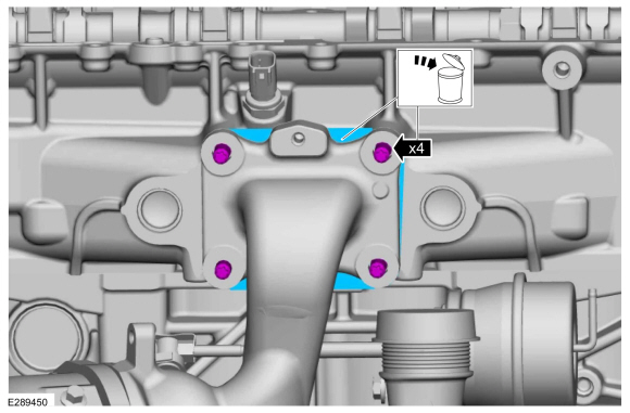
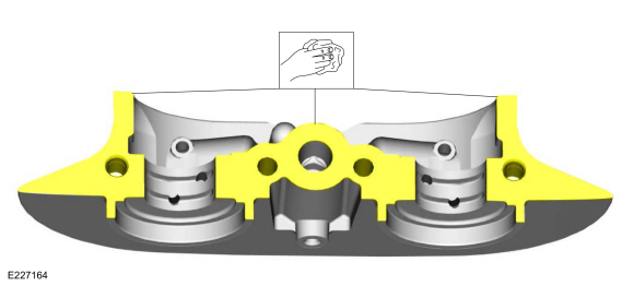
Tighten the bolts evenly, half a turn at a time, until the camshaft bearing caps and the VCT bridge are seated against the cylinder head.
Material: Engine Oil - SAE 5W-20 - Synthetic Blend Motor Oil
/ XO-5W20-Q1SP
(WSS-M2C945-B1)
Torque:
Stage 1: Tighten bolts 1 through 16 to:
:
62 lb.in (7
Nm)
Stage 2: Tighten bolts 17 through 20 to:
:
89 lb.in (10
Nm)
Stage 3: Tighten bolts 1 through 16 an additional:
:
45
°
Stage 4: Tighten bolts 17 and 18 an additional:
:
70
°
Stage 5: Tighten bolts 19 and 20 an additional:
:
53
°
 |
|
-
Install the camshaft seals.
Refer to: Camshaft Seal (303-01A Engine - 1.5L EcoBoost (118kW/160PS) – I4, Removal and Installation).
-
NOTE:
Make sure that the components are installed to the position noted before removal.
Position the timing belt on the VCT units.
-
 WARNING:
The tensioner is under spring tension. Be careful
when handling the tensioner. Failure to follow this instruction may
result in personal injury.
WARNING:
The tensioner is under spring tension. Be careful
when handling the tensioner. Failure to follow this instruction may
result in personal injury.
-
Verify that the timing belt is properly aligned.
-
Remove the holding pin.
-
-
Make sure that the components are installed to the position noted before removal.
-
Remove Special Service Tool: 303-1556
Locking Tool, Timing Belt.
-
Remove Special Service Tool: 303-748
Locking Tool, Crankshaft.
-
Remove Special Service Tool: 303-1097
Locking Tool, Variable Camshaft Timing Oil Control Unit.
-
NOTE:
There are different length of bolts noted in disassembly.
Install the engine mount bracket and the bolts.
Torque:
41 lb.ft (55
Nm)
-
Install the engine front cover.
-
Install the engine front cover bolts.
Torque:
89 lb.in (10
Nm)
-
Close the engine front cover side panel and install the stud bolt.
Torque:
89 lb.in (10 Nm)
-
Install the bracket, the nut and the bolt.
Torque:
Bolt
:
17 lb.ft (23
Nm)
Nut
:
62 lb.in (7
Nm)
-
Install the engine mount stud finger tight.
-
Position back the generator and install the stud.
Torque:
89 lb.in (10
Nm)
-
-
Install the bracket, if equipped and the upper generator stud bolt.
Torque:
35 lb.ft (47
Nm)
-
Install the generator nut.
Torque:
35 lb.ft (47
Nm)
-
Tighten the lower generator bolt.
Torque:
35 lb.ft (47
Nm)
-
NOTE:
Only tighten the bolts finger tight at this stage.
Install the coolant pump pulley and the bolts.
-
Install the following items:
-
Install the accessory drive belt.
Refer to: Accessory Drive Belt (303-05A Accessory Drive - 1.5L EcoBoost (118kW/160PS) – I4, Removal and Installation).
-
Install the engine mount.
Refer to: Engine Mount (303-01A Engine - 1.5L EcoBoost (118kW/160PS) – I4, Removal and Installation).
-
Install the intake manifold bolt.
Torque:
159 lb.in (18
Nm)
-
Position back the crankcase vent oil separator inlet pipe and install the bolt.
Torque:
35 lb.in (4
Nm)
-
Install and connect the engine vent hose.
Use the General Equipment: Hose Clamp Remover/Installer
-
NOTE:
Hand start the intake manifold bolt first.
Install the intake manifold bracket and bolts.
Torque:
Cylinder head bolt
:
159 lb.in (18
Nm)
Intake manifold bolt
:
89 lb.in (10
Nm)
-
Install the TB (throttle body).
Refer to: Throttle Body (303-04A Fuel Charging and Controls - 1.5L EcoBoost (118kW/160PS) – I4, Removal and Installation).
-
Lubricate the coolant outlet O-ring seal with clean coolant.
Material: Motorcraft® Orange Concentrated Antifreeze/Coolant
/ VC-3-B
(WSS-M97B44-D)
-
-
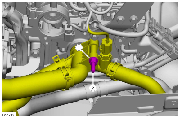
Position back the coolant outlet and install the stud.
Torque:
44 lb.in (5
Nm)
-
Install the nut.
Torque:
159 lb.in (18
Nm)
-
Position back and connect the coolant hose.
Use the General Equipment: Hose Clamp Remover/Installer
-
Install the new TC mounting gasket and the studs.
Torque:
89 lb.in (10
Nm)
-
Install the TC nuts.
Torque:
Stage 1::
62 lb.in (7
Nm)
Stage 2::
124 lb.in (14
Nm)
Stage 3::
17 lb.ft (23
Nm)
-
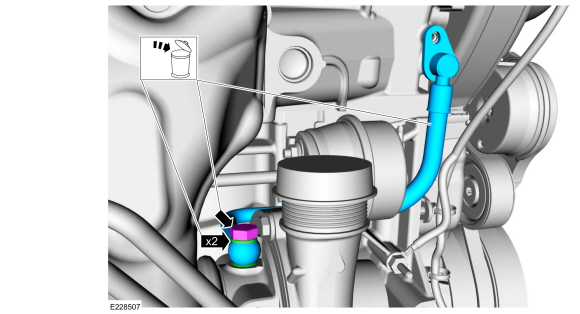
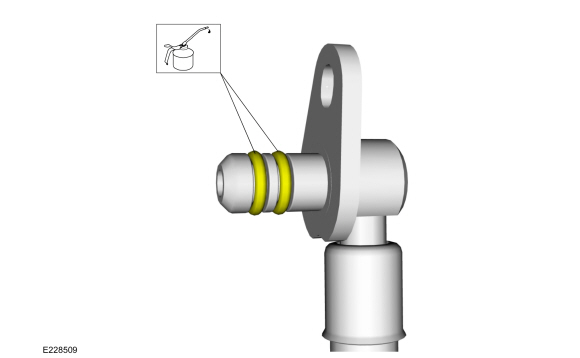
Lubricate the new O-ring seals with clean engine oil.
Material: Engine Oil - SAE 5W-20 - Synthetic Blend Motor Oil
/ XO-5W20-Q1SP
(WSS-M2C945-B1)
-
Install the new TC oil supply tube assembly.
Torque:
19 lb.ft (26
Nm)
-
NOTICE:
When installing the oil supply tube, the spigot on
the oil supply tube must be fully engaged to the cylinder head with both
O-rings inserted before the fastener is tightened.
Position the oil supply tube and install the bolt.
Torque:
89 lb.in (10
Nm)
-
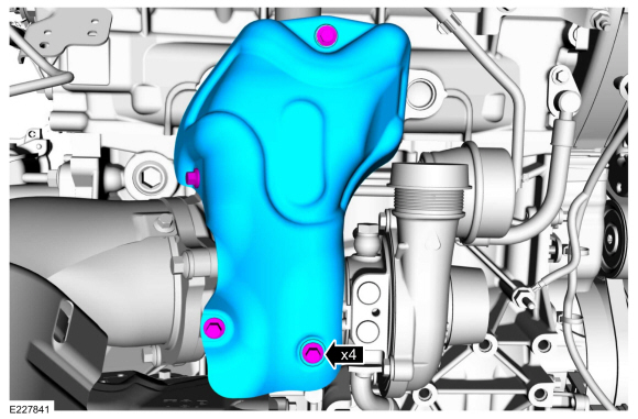
Install the turbocharger heat shield and the bolts.
Torque:
89 lb.in (10
Nm)
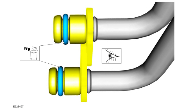
-
Install the new turbocharger coolant tube O-ring seals and lubricate with clean engine coolant.
Material: Motorcraft® Orange Concentrated Antifreeze/Coolant
/ VC-3-B
(WSS-M97B44-D)
-
Position back the TC coolant tubes and install the bolt.
Torque:
89 lb.in (10
Nm)
-
-
Install the turbocharger coolant tube bolt.
Torque:
17 lb.ft (23
Nm)
-
Install the turbocharger coolant tube bolt.
Torque:
97 lb.in (11
Nm)
-
Connect the retainer to the coolant tube bracket.
-
Attach the wiring harness retainers.
-
Position back the coolant hoses and connect the quick release couplings.
-
Connect the TB (throttle body) electrical connector and the wiring harness retainer.
-
-
Connect and attach the KS electrical connector.
-
Connect and attach the KS electrical connector.
-
Position back and connect the coolant hose.
-
Connect the IAT sensor electrical connector and the wire harness retainer.
-
Position back the wiring harness and attach the wiring harness retainer. Install the wiring harness bolt.
Torque:
89 lb.in (10
Nm)
-
Connect the electrical connector and attach the wiring harness retainer.
-
Connect the PCM electrical connector.
-
Install the following items:
-
Install the brake vacuum pump.
Refer to: Brake Vacuum Pump - 1.5L EcoBoost (118kW/160PS) – I4 (206-07 Power Brake Actuation, Removal and Installation).
-
Install the High-Pressure fuel pump drive unit.
Refer to: High-Pressure Fuel Pump Drive Unit (303-04A Fuel Charging and Controls - 1.5L EcoBoost (118kW/160PS) – I4, Removal and Installation).
-
Connect the CHT sensor electrical connector and install the cover.
-
-
Connect the electrical connectors to the bracket.
-
Connect the turbocharger vacuum hose and retainers.
Use the General Equipment: Hose Clamp Remover/Installer
-
If equipped, install the heat shield and the retainers.
-
Connect the CKP sensor electrical connector and the wire harness retainers.
-
Tighten the coolant pump pulley bolts.
Torque:
18 lb.ft (24 Nm)
-
Install the engine plug bolt.
Torque:
177 lb.in (20 Nm)
-
Position the halfshaft bearing bracket and install the bolts.
Torque:
35 lb.ft (48 Nm)
-
-
Install the halfshaft bearing bracket strap and the retaining nuts.
Torque:
44 lb.in (5
Nm)
-
Tighten the nut.
Torque:
18 lb.ft (25
Nm)
-
Tighten the nut.
Torque:
18 lb.ft (25
Nm)
-
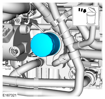
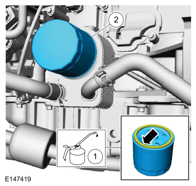
Remove and discard the engine oil filter.
Use the General Equipment: Oil Drain Equipment
Use the General Equipment: Strap Wrench
-
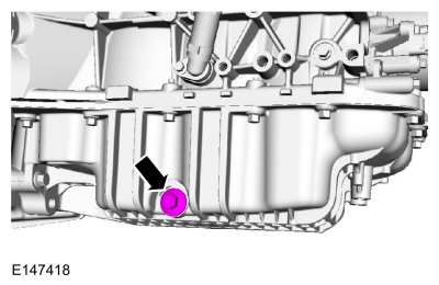
Remove the drain plug, drain engine oil and install drain plug.
Use the General Equipment: Oil Drain Equipment
Torque:
21 lb.ft (28 Nm)
-
NOTE:
Lubricate the new engine oil filter with clean engine oil.
Lubricate the O-ring seal and install the new engine oil filter.
Material: Engine Oil - SAE 5W-20 - Synthetic Blend Motor Oil
/ XO-5W20-Q1SP
(WSS-M2C945-B1)
Torque:
133 lb.in (15 Nm)
-
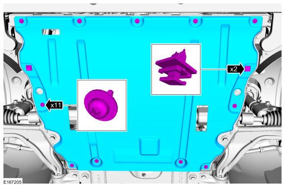
Install the underbody shield and the retainers.
-
-
Install the EVAP canister purge valve.
Refer to: Evaporative Emission Canister Purge Valve (303-13A Evaporative Emissions - 1.5L EcoBoost (118kW/160PS) – I4, Removal and Installation).
-
Install the CAC inlet pipe.
Refer to: Charge Air Cooler (CAC) Intake Pipe (303-12A Intake Air Distribution and Filtering - 1.5L EcoBoost (118kW/160PS) – I4, Removal and Installation).
-
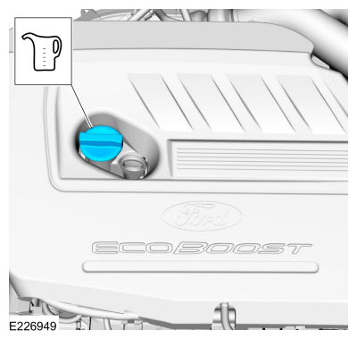
Fill the engine with clean engine oil.
Material: Engine Oil - SAE 5W-20 - Synthetic Blend Motor Oil
/ XO-5W20-Q1SP
(WSS-M2C945-B1)
-
Connect the battery ground cable.
Refer to: Battery Disconnect and Connect (414-01 Battery, Mounting and Cables, General Procedures).
-
Fill and bleed the cooling system.
Refer to: Engine Cooling System Draining, Vacuum Filling and Bleeding (303-03A Engine Cooling - 1.5L EcoBoost (118kW/160PS) – I4, General Procedures).
Removal
Remove the following items:
Refer to: Flexplate (303-01A Engine - 1.5L EcoBoost (118kW/160PS) – I4, Removal and Installation).
Refer to: Oil Pan (303-01A Engine - 1...
Special Tool(s) /
General Equipment
Trolley Jack
Wooden Block
Removal
With the vehicle in NEUTRAL, position it on a hoist.
Refer to: Jacking and Lifting - Overview (100-02 Jacking and Lifting, Description and Operation)...
Other information:
Removal
NOTICE:
Suspension fasteners are critical parts that affect the
performance of vital components and systems. Failure of these fasteners
may result in major service expense. Use the same or equivalent parts if
replacement is necessary. Do not use a replacement part of lesser
quality or substitute design...
Note: Each road tire is equipped with a tire
pressure sensor located inside the wheel
and tire assembly cavity. The pressure
sensor is attached to the valve stem. The
pressure sensor is covered by the tire and is
not visible unless the tire is removed...


 Crankshaft Rear Seal. Removal and Installation
 Engine Mount. Removal and Installation