Ford Fusion: Automatic Transmission - 6-Speed Automatic Transmission – 6F35 / Transmission - 1.5L EcoBoost (118kW/160PS) – I4. Removal and Installation
Special Tool(s) /
General Equipment
 |
100-001
(T50T-100-A)
Slide Hammer |
 |
205-241
(T86P-3514-A)
Remover, Halfshaft
T86P-1000-S
TKIT-2009TC-F
TKIT-1986-F |
 |
205-290
(T89P-3415-B)
Remover, Halfshaft (Plate)
TKIT-1989-LM
TKIT-1989-FLM |
 |
303-1502
Lifting Device Engine
TKIT-2012A-FL
TKIT-2012A-ROW |
 |
303-290B-18
Adapter for 303-290B
TKIT-2012A-FL
TKIT-2012A-ROW |
 |
303-F072
Support Bar, Engine |
 |
307-566
Retainer, Torque Converter
TKIT-2006C-FFMFLM
TKIT-2006C-LM
TKIT-2006C-ROW |
| Magnetic Socket |
| Transmission Jack |
Materials
| Name |
Specification |
Motorcraft® Multi-Purpose Grease Spray
XL-5-A |
ESB-M1C93-B
|
Motorcraft® Threadlock and Sealer
TA-25-B |
-
|
Motorcraft® MERCON® LV Automatic Transmission Fluid
XT-10-QLVC |
WSS-M2C938-A
MERCON® LV,
|
Removal
All vehicles
-
With the vehicle in NEUTRAL, position it on a hoist.
Refer to: Jacking and Lifting - Overview (100-02 Jacking and Lifting, Description and Operation).
-
Remove the following items:
-
Refer to: Battery Tray (414-01 Battery, Mounting and Cables, Removal and Installation).
-
Refer to: Air Cleaner Outlet Pipe (303-12A Intake Air Distribution and Filtering - 1.5L EcoBoost (118kW/160PS) – I4, Removal and Installation).
-
Disconnect the selector lever cable end from the
manual control lever, remove the bracket bolts and position aside the
selector lever cable and bracket.
-
Disconnect the retainers and position the wiring harness aside.
-
Remove the upper transmission-to-engine bolts.
-
Disconnect the TSS sensor electrical connector.
-
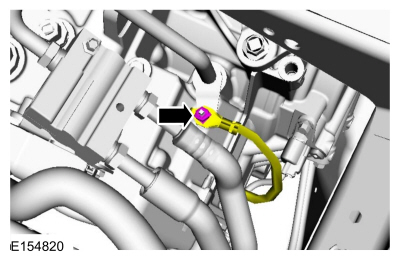
Remove the nut and the ground cable.
-
Remove the front subframe.
Refer to: Front Subframe - 2.7L EcoBoost (238kW/324PS) (502-00 Uni-Body, Subframe and Mounting System, Removal and Installation).
-
NOTE:
If transmission disassembly or installation of a
new transmission is necessary, drain the transmission fluid.
Remove the drain plug and drain the transmission. Install the drain plug.
Torque:
159 lb.in (18 Nm)
-
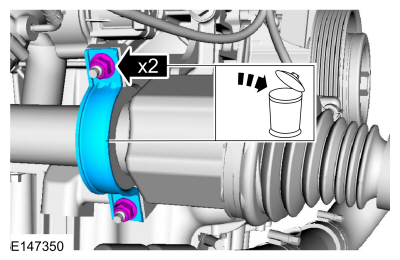
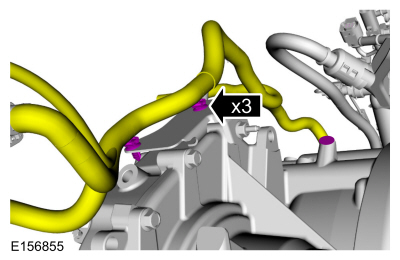
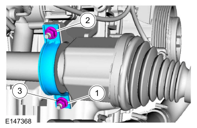
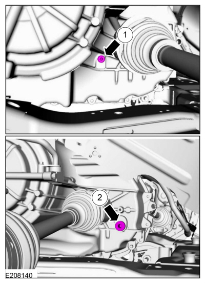
Remove and discard the halfshaft bracket and the nuts.
-
Position the RH halfshaft aside and support with a length of mechanics wire.
-
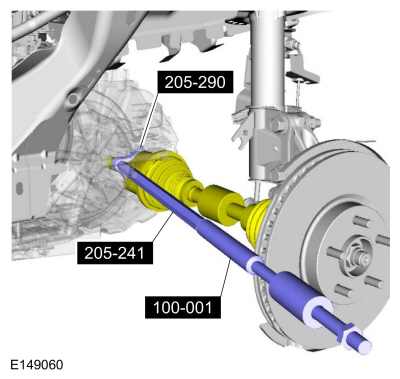
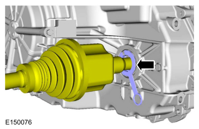
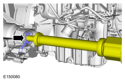
Using the special tools, separate the LH halfshaft from the transmission.
Use Special Service Tool: 100-001
(T50T-100-A)
Slide Hammer.
, 205-241
(T86P-3514-A)
Remover, Halfshaft.
, 205-290
(T89P-3415-B)
Remover, Halfshaft (Plate).
-
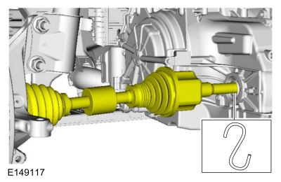
Position the LH halfshaft aside and support with a length of mechanics wire.
-
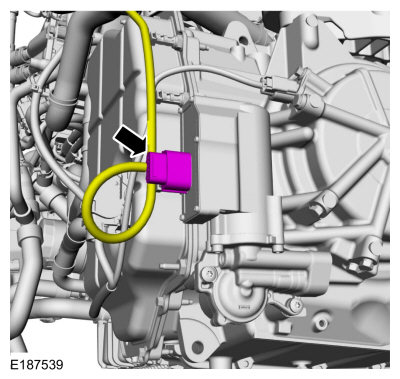
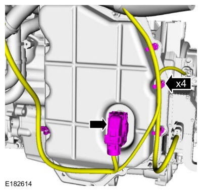
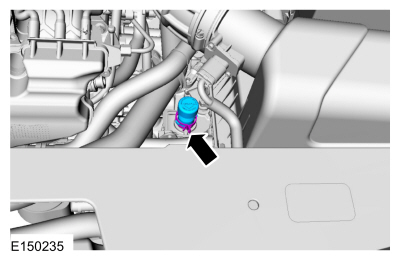
Disconnect the electrical connector and wiring harness retainers.
Auto-Start-Stop
-
Disconnect the transmission fluid auxiliary pump electrical connector.
All vehicles
-
Remove the bolts and position aside the CAC coolant pump.
-
Disconnect the wiring harness retainers.
-
Remove the starter motor.
Refer to: Starter Motor (303-06A Starting System - 1.5L EcoBoost (118kW/160PS) – I4, Removal and Installation).
-
Remove the stater motor insulator.
-
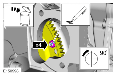
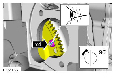
NOTICE:
Only rotate the engine in a clockwise direction or engine damage will occur.
NOTE:
Index mark one stud and the flexplate for assembly reference.
Using a magnetic socket, remove and discard the torque converter nuts.
Use the General Equipment: Magnetic Socket
-
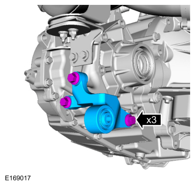
NOTE:
If transmission disassembly or installation of a new transmission is necessary, remove the bracket.
If necessary, remove the bolts and the roll restrictor bracket.
-
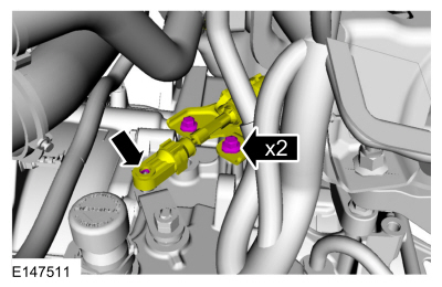
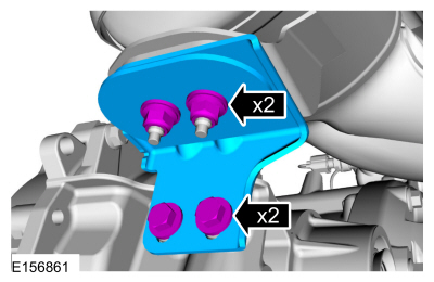
Remove the nuts and bolts and the catalytic converter bracket.
-
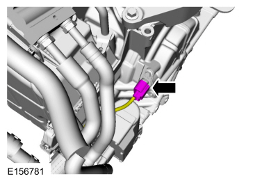
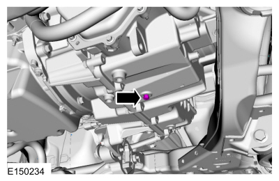
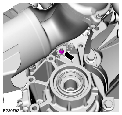
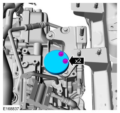
Remove the transmission fluid warmer bracket nut.
-
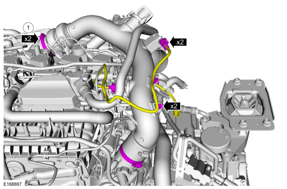
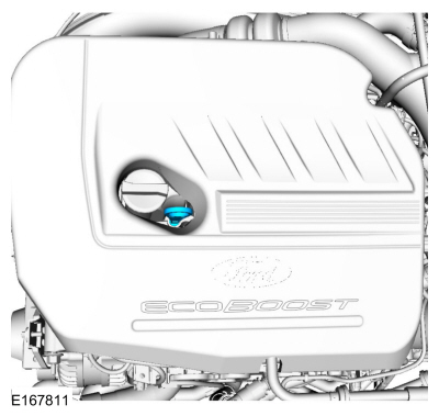
Remove the engine appearance cover.
-
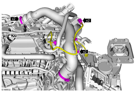
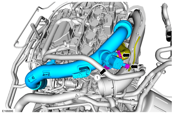
Loosen the clamps, disconnect the electrical connectors and the harness retainers.
-
NOTICE:
Whenever turbocharger air intake system
components are removed, always cover open ports to protect from debris.
It is important that no foreign material enter the system. The
turbocharger compressor vanes are susceptible to damage from even small
particles. All components should be inspected and cleaned, if necessary,
prior to installation or reassembly.
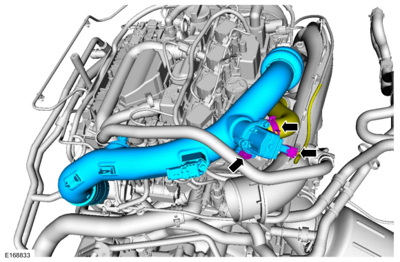
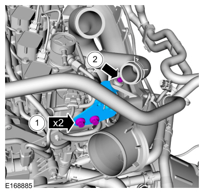
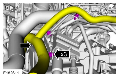
Disconnect the electrical connector and hose, remove the bolt and the CAC tube.
-
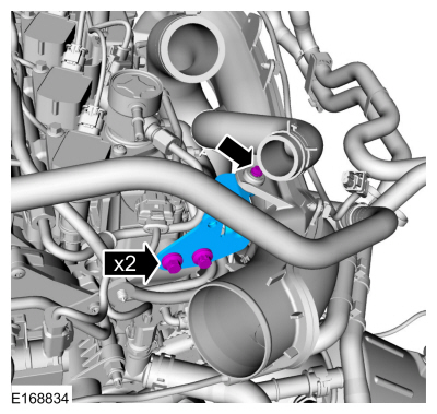
Remove the bolts and the bracket.
-
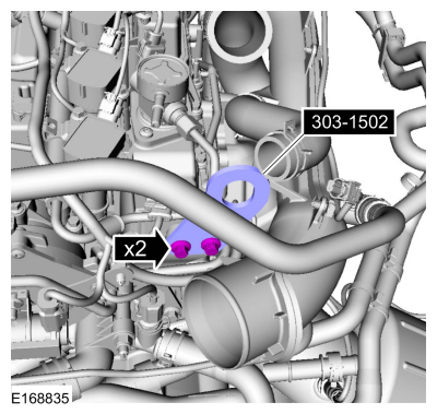
Install the special tool.
Use Special Service Tool: 303-1502
Lifting Device Engine.
-
Remove the retainers and the RH and LH filler panels.
-
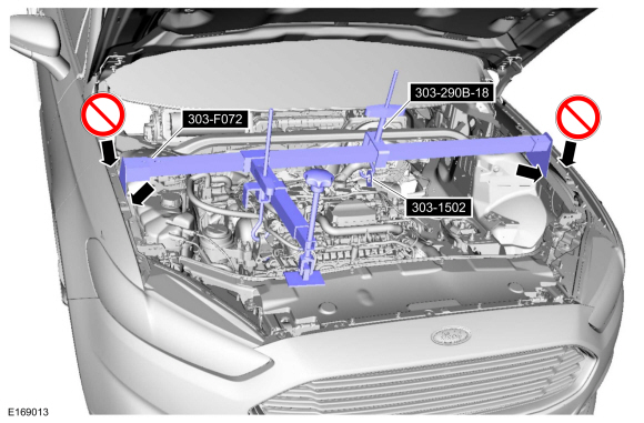
Using the special tools, support the engine.
Use Special Service Tool: 303-F072
Support Bar, Engine.
, 303-290B-18
Adapter for 303-290B.
, 303-1502
Lifting Device Engine.
-
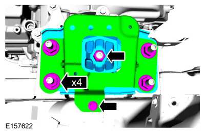
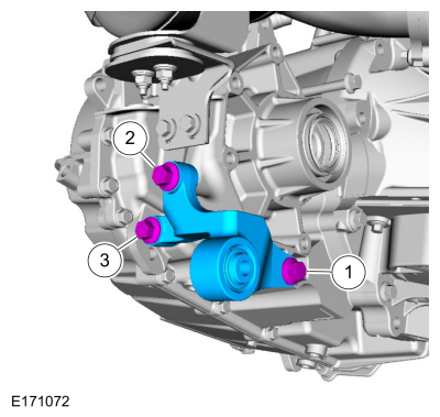
Remove and the bolt and nuts, remove the bracket and the transmission support insulator.
-
Remove the bolts and the transmission support insulator damper.
-
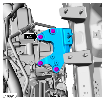
Remove the bolts and the transmission support insulator bracket.
-
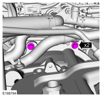
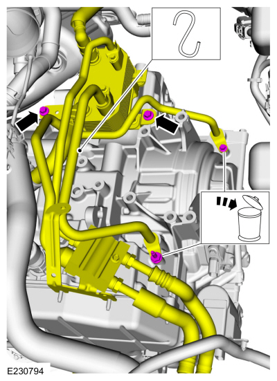
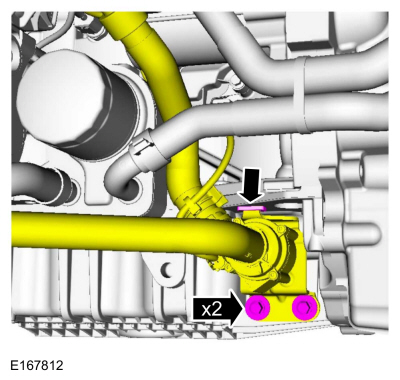
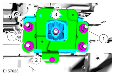
Remove the transmission fluid cooler bypass bracket nuts.
-
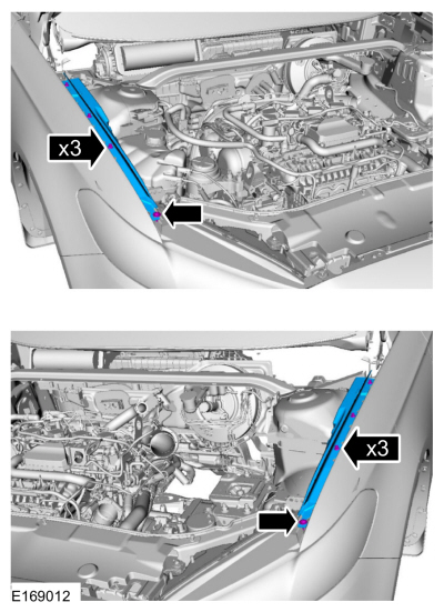
Remove and discard the transmission fluid cooler tube bolts, and remove the transmission fluid warmer bolts.
-
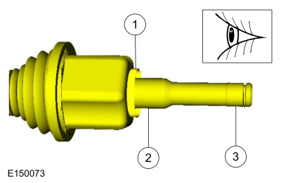
Inspect the transmission case to be sure that the
transmission fluid cooler tube seals and backing rings were removed with
the transmission fluid cooler tubes and are not stuck in the
transmission case. If the transmission fluid cooler tube seals or
backing rings are stuck in the transmission case, remove the seals and
backing rings.
-
NOTICE:
Secure the transmission to the transmission jack with a safety strap.
Support the transmission with a transmission jack.
Use the General Equipment: Transmission Jack
-
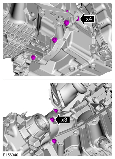
NOTE:
The transmission-to-engine bolts differ in length. Mark the bolts for correct installation.
Remove the transmission-to-engine bolts.
-
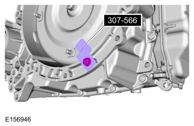
Separate the transmission from the engine and install the special tool.
Use Special Service Tool: 307-566
Retainer, Torque Converter.
-
NOTICE:
Failure to clean the transmission fluid cooler tubes can result in transmission failure.
If the transmission is to be overhauled or if
installing a new or re-manufactured transmission, carryout the
transmission fluid cooler backflushing and cleaning. Clean the
transmission-mounted transmission fluid cooler tubes by hand.
Refer to: Transmission Fluid Cooler - Backflushing and Cleaning (307-02A Transmission Cooling - 6-Speed Automatic Transmission – 6F35, General Procedures).
Installation
All vehicles
-
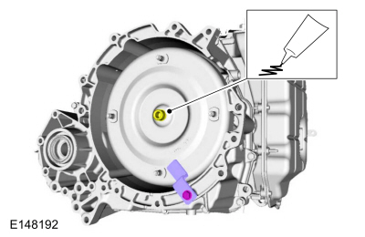
Lubricate the torque converter pilot hub with Multi-Purpose Grease.
Material: Motorcraft® Multi-Purpose Grease Spray
/ XL-5-A
(ESB-M1C93-B)
-
NOTICE:
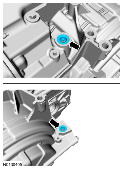
If the transmission is not positioned on the dowel pins, damage to the transmission may occur.
If the dowel pins were pulled out of the engine
block during removal, install new dowel pins in the engine block.
-
NOTICE:
Secure the transmission to the transmission jack with a safety strap.
Support the transmission with a transmission jack.
Use the General Equipment: Transmission Jack
-
Position the transmission behind the engine and remove the special tool.
Use Special Service Tool: 307-566
Retainer, Torque Converter.
-
Align the index-mark made during removal.
-
NOTE:
Install the different length bolts in the correct locations as noted during removal.
Install the transmission-to-engine bolts.
Use the General Equipment: Transmission Jack
Torque:
35 lb.ft (48 Nm)
-
NOTICE:
Only rotate the engine in a clockwise direction or engine damage will occur.
NOTE:
The torque converter nuts are accessed from the top of the vehicle.
Using a magnetic socket install the new torque converter nuts.
Use the General Equipment: Magnetic Socket
Torque:
35 lb.ft (48 Nm)
-
Install the CAC coolant pump bolts.
Torque:
17 lb.ft (23 Nm)
-
NOTE:
If removed, inspect the transmission mounted
transmission fluid cooler tube backing rings and seals for damage and
install new backing rings or seals if necessary.
-
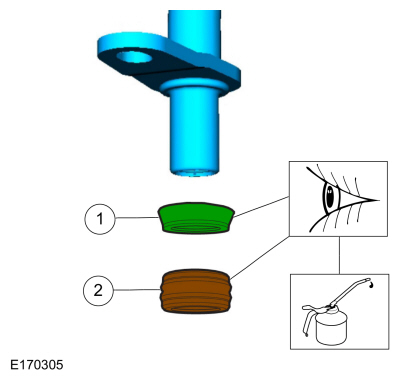
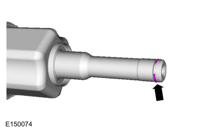
Install the backing ring (7J324)
-
Lubricate and install the seal (7D285)
Material: Motorcraft® MERCON® LV Automatic Transmission Fluid
/ XT-10-QLVC
(WSS-M2C938-A)
(MERCON® LV, )
-
-
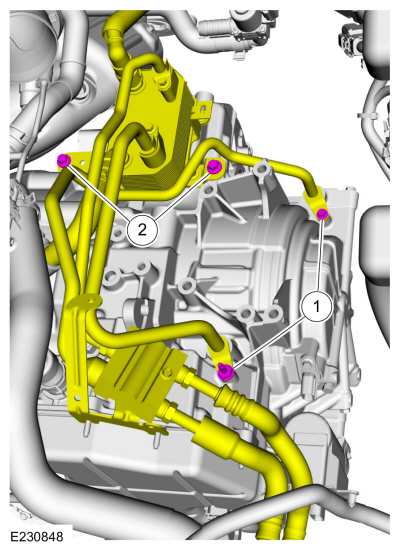
Install the new transmission fluid cooler tube bolts.
Torque:
89 lb.in (10 Nm)
-
Install the transmission fluid warmer and the bolts.
Torque:
18 lb.ft (25 Nm)
-
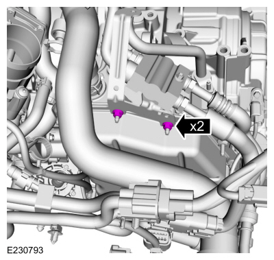
Install the transmission fluid cooler bypass bracket nuts.
Torque:
80 lb.in (9 Nm)
-
Install the transmission support insulator bracket and the bolts.
Torque:
59 lb.ft (80 Nm)
-
Install the transmission support insulator damper and the bolts.
Torque:
80 lb.in (9 Nm)
-
Install the transmission support insulator and
bracket. Apply Motorcraft® Threadlock and Sealer to the nuts.
-
Material: Motorcraft® Threadlock and Sealer
/ TA-25-B
Torque:
59 lb.ft (80 Nm)
-
Torque:
18 lb.ft (25 Nm)
-
Material: Motorcraft® Threadlock and Sealer
/ TA-25-B
Torque:
98 lb.ft (133 Nm)
-
Install the RH and LH filler panels and the retainers.
-
Install the bracket and the bolts.
-
Torque:
97 lb.in (11 Nm)
-
Torque:
71 lb.in (8 Nm)
-
Install the CAC tube and bolt, connect the electrical connector and the hose.
-
Torque:
71 lb.in (8 Nm)
-
Tighten the CAC tube clamps, connect the electrical connectors and the retainers.
-
Torque:
44 lb.in (5 Nm)
-
Install the engine appearance cover.
-
Install the transmission fluid warmer bracket nut.
Torque:
80 lb.in (9 Nm)
-
Install the catalytic converter support bracket, the bolts and the nuts.
Torque:
18 lb.ft (25 Nm)
-
NOTE:
Tighten in the sequence shown.
Install the roll restrictor bracket and the bolts.
Torque:
92 lb.ft (125 Nm)
-
Install the starter insulator.
-
Install the starter motor.
Refer to: Starter Motor (303-06A Starting System - 1.5L EcoBoost (118kW/160PS) – I4, Removal and Installation).
-
Connect the wiring harness retainers.
Auto-Start-Stop
-
Connect the transmission fluid auxiliary pump electrical connector.
All vehicles
-
Connect the electrical connector and wiring harness retainers.
-
Inspect the LH halfshaft hub for wear or damage and install a new halfshaft, if necessary.
-
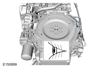
Inspect the differential seal surface.
-
Inspect the halfshaft bushing surface. If this
surface is damaged, inspect the halfshaft bushing for damage.
-
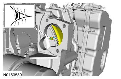
Inspect the differential side gear splines.
-
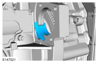
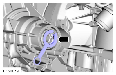
Install the new inner halfshaft retaining circlip.
-
NOTE:
If the transmission has been replaced or overhauled, the halfshaft seals do not need to be replaced.
Install a new LH halfshaft seal.
Refer to: Halfshaft Seal LH (307-01A Automatic Transmission - 6-Speed Automatic Transmission – 6F35, Removal and Installation).
-
Install the seal protector.
-
NOTE:
Do not fully install shaft at this time.
Using the seal protector, insert the splines of the
halfshaft through the halfshaft seal and remove the seal protector.
-
NOTE:
When seated correctly, the halfshaft bearing
retaining clip can be felt as it snaps into the differential side gear
groove.
Insert the halfshaft until the halfshaft retaining clip is fully seated.
-
-
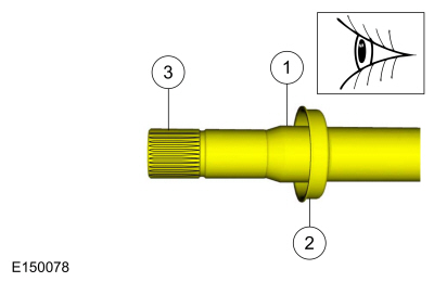
Inspect the RH halfshaft seal surface.
-
Inspect the dust shield.
-
Inspect the differential side gear splines.
-
NOTE:
If the transmission has been replaced or overhauled, the halfshaft seals do not need to be replaced.
Install a new RH halfshaft seal.
Refer to: Halfshaft Seal RH - FWD (307-01A Automatic Transmission - 6-Speed Automatic Transmission – 6F35, Removal and Installation).
-
Install the seal protector.
-
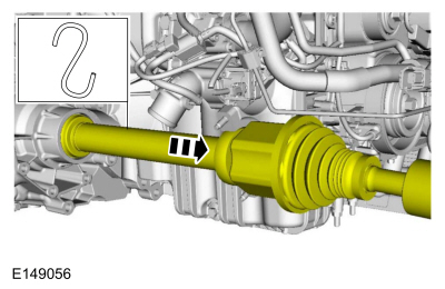
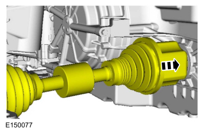
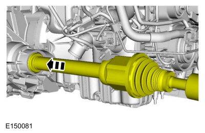
Push the RH halfshaft into the transmission so the splines go through the seal protector and remove the seal protector.
-
Install the RH halfshaft assembly.
-
Install the new halfshaft retaining strap and the new halfshaft retaining strap nuts.
Torque:
Stage 1:
44 lb.in (5 Nm)
Stage 2:
18 lb.ft (25 Nm)
Stage 3:
18 lb.ft (25 Nm)
-
Install the front subframe.
Refer to: Front Subframe - 2.7L EcoBoost (238kW/324PS) (502-00 Uni-Body, Subframe and Mounting System, Removal and Installation).
-
Install the ground cable and the nut.
Torque:
80 lb.in (9 Nm)
-
Connect the TSS sensor electrical connector.
-
Install the upper transmission-to-engine bolts.
Torque:
35 lb.ft (48 Nm)
-
Connect the wiring harness retainers.
-
Install the selector lever cable bracket and the bolts.
Torque:
18 lb.ft (25 Nm)
-
Install the following items:
-
Refer to: Battery Tray (414-01 Battery, Mounting and Cables, Removal and Installation).
-
Refer to: Air Cleaner Outlet Pipe (303-12A Intake Air Distribution and Filtering - 1.5L EcoBoost (118kW/160PS) – I4, Removal and Installation).
-
Adjust the selector lever cable.
Refer to: Selector Lever Cable Adjustment - 1.5L EcoBoost (118kW/160PS) – I4 (307-05A Automatic Transmission External Controls - 6-Speed Automatic Transmission – 6F35, General Procedures).
-
Compress the constant tension clamp and remove the transmission vent from the fill tube.
-
NOTICE:
The following fluid amounts listed below are for
initial fill only. The transmission fluid must be even with the oil
leveling plug hole and the transmission must be at normal operating
temperature 85-93°C (185-200°F) or transmission damage can occur.
-
Transmission overhaul (includes main control and torque converter drain)
Volume:
6.34
qt (
6
L)
-
Main control overhaul or replace (with out transmission overhaul)
Volume:
5.28
qt (
5
L)
-
Transmission draining and filling (for engine and halfshaft related repairs)
Volume:
4.23
qt (
4
L)
-
Material: Motorcraft® MERCON® LV Automatic Transmission Fluid
/ XT-10-QLVC
(WSS-M2C938-A)
(MERCON® LV, )
-
Start the engine and slowly select each gear,
stopping in each position and allowing the transmission to engage.
-
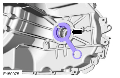
With the vehicle on a level hoist, the engine
running in PARK, remove the oil leveling plug and allow the transmission
fluid to drain until its even with the oil leveling plug hole. If the
transmission fluid does not drain from the oil leveling plug hole add
transmission fluid in increments of .25 L (0.264 qt) until the
transmission fluid is even with the oil leveling plug hole. Install the
oil leveling plug.
-
Standard transmission case (M10 plug)
Torque:
71 lb.in (8 Nm)
-
Fuel economy transmission case (M20 plug)
Torque:
26 lb.ft (35 Nm)
-
With the clamp facing the front of the vehicle,
compress the constant tension clamp and install the transmission vent on
the fill tube.
-
NOTE:
Only download the solenoid strategy at this
time. The Adaptive Learning Drive Cycle will be completed later in this
procedure.
If a new solenoid body is installed, the solenoid body strategy must be updated.
Refer to: Transmission Strategy Download (307-01A Automatic Transmission - 6-Speed Automatic Transmission – 6F35, General Procedures).
Auto-Start-Stop
-
NOTE:
TFT must be greater than 38ºC (100ºF) for the PCM to command the pump on.
Using the scan tool verify the TFT is above 38ºC (100ºF).
-
If TFT is below 38ºC (100ºF), run engine at 3000 RPM until specified temperature is achieved (approximately 2-4 minutes).
-
Prime the Transmission Fluid Auxiliary Pump.
-
Key ON, Engine OFF.
-
Using the scan tool, command TRANS_PMP_CMD to
80% for 30 seconds. If the pump cannot be commanded on, verify TFT is above 38ºC (100ºF).
-
Clear DTCs.
-
Carry out a road test until there is a stop / start
event. If the restart is harsh, repeat the Transmission Fluid Pump prime
procedure.
-
Continue road test and evaluate each stop / start
event. Repeat prime procedure until three consecutive normal stop /
start events are achieved.
All vehicles
-
Using a scan tool, drive the vehicle until the
transmission is at normal operating temperature 85-93°C (185-200°F).
-
After completing the repairs perform the Misfire Monitor Neutral Profile Correction procedure.
-
If a new solenoid body is installed, complete the Adaptive Learning Drive Cycle.
Refer to: Adaptive Learning Drive Cycle (307-01A Automatic Transmission - 6-Speed Automatic Transmission – 6F35, General Procedures).
-
Check the transmission fluid level.
Refer to: Transmission Fluid Level Check (307-01A Automatic Transmission - 6-Speed Automatic Transmission – 6F35, General Procedures).
Removal
To remove the LH halfshaft bushing, transmission disassembly is required.
Refer to: Transmission (307-01A Automatic Transmission - 6-Speed Automatic Transmission – 6F35, Overhaul)...
Other information:
System Operation
System Diagram
Item
Description
1
VDM
2
LH front valve solenoid
3
PSCM
4
PCM
5
ABS module
6
LH front height sensor
7
RH front height sensor
8
LH rear height sensor
9
RH rear height sensor
10
BCM
11
RH front valve solenoid
12
LH rear valve solenoid
13
R..
Preliminary Inspection
Visually inspect the CV joints for obvious signs of mechanical damage.
If an obvious cause for an observed or reported concern is
found, correct the cause (if possible) before proceeding to the next
step
If the cause is not visually evident, verify the symptom and REFER to Symptom Chart: NVH.
Symptom Chart(s)
Diagnostics in this manual assume..


 Transmission Case Bushing. Removal and Installation