Ford Fusion: Automatic Transmission - 6-Speed Automatic Transmission – 6F35 / Transmission Internal Wiring Harness Frame. Removal and Installation
Ford Fusion 2013–2020 Service Manual / Powertrain / Automatic Transmission / Automatic Transmission - 6-Speed Automatic Transmission – 6F35 / Transmission Internal Wiring Harness Frame. Removal and Installation
Special Tool(s) / General Equipment
 |
307-636 Alignment Pins- Valve Body TKIT-2008ET-FLM TKIT-2008ET-ROW |
Removal
-
Remove the main control cover.
Refer to: Main Control Cover - 1.5L EcoBoost (118kW/160PS) – I4 (307-01A Automatic Transmission - 6-Speed Automatic Transmission – 6F35, Removal and Installation).
Refer to: Main Control Cover - 2.5L Duratec (125kW/170PS) (307-01A Automatic Transmission - 6-Speed Automatic Transmission – 6F35, Removal and Installation).
-
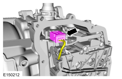
Disconnect the TR sensor electrical connector.
 |
-
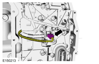
Disconnect the OSS sensor electrical connector.
 |
-
Remove the main control-to-cover seal.
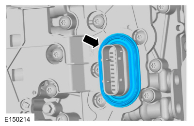 |
-
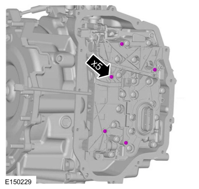
NOTICE: Be careful not to bend or twist the transmission internal wiring harness frame or the solenoid terminals when removing the transmission internal wiring harness frame or damage can occur.
Remove the transmission internal wiring harness frame screws and the transmission internal wiring harness frame from the solenoids by lifting it straight up evenly.
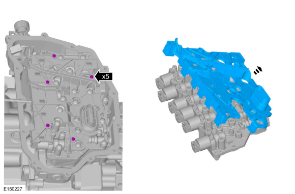 |
Installation
-
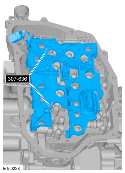
Install the special tools in the solenoid body to align
the transmission internal wiring harness frame during installation.
Use Special Service Tool: 307-636 Alignment Pins- Valve Body.
 |
-
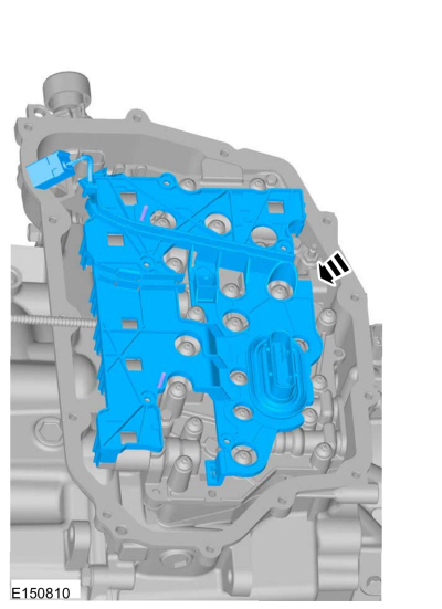
Position the transmission internal wiring harness frame
on the special tools and carefully install the transmission internal
wiring harness frame by pushing straight down into the solenoids.
 |
-
Install the transmission internal wiring harness frame screws.
Torque: 31 lb.in (3.5 Nm)
 |
-
Connect the OSS sensor electrical connector.
 |
-
Connect the TR sensor electrical connector.
 |
-
Install the main control-to-cover seal.
 |
-
Install the main control cover.
Refer to: Main Control Cover - 1.5L EcoBoost (118kW/160PS) – I4 (307-01A Automatic Transmission - 6-Speed Automatic Transmission – 6F35, Removal and Installation).
Refer to: Main Control Cover - 2.5L Duratec (125kW/170PS) (307-01A Automatic Transmission - 6-Speed Automatic Transmission – 6F35, Removal and Installation).
 Transmission Fluid Auxiliary Pump. Removal and Installation
Removal
With the vehicle in NEUTRAL, position it on a hoist.
Refer to: Jacking and Lifting - Overview (100-02 Jacking and Lifting, Description and Operation)...
 Transmission Range (TR) Sensor. Removal and Installation
Special Tool(s) /
General Equipment
Punch
Locking Pliers
Removal
Remove the main control cover.
Refer to: Main Control Cover - 1...
Other information:
Ford Fusion 2013–2020 Service Manual: Overdrive Clutch Assembly. Diagnosis and Testing
Overdrive Clutch For overdrive clutch operation, REFER to: Transmission Description - System Operation and Component Description (307-01A Automatic Transmission - 6-Speed Automatic Transmission – 6F35, Description and Operation). REFER to: Overdrive Clutch Assembly (307-01A Automatic Transmission - 6-Speed Automatic Transmission – 6F35, Description and Operation)...
Ford Fusion 2013–2020 Owners Manual: Settings
Press the button to enter the settings menu. Once you select a tile, press the button next to a menu item to view an explanation of the feature or setting. Sound Select this tile to adjust sound the settings. Clock Select this tile to adjust the clock settings...
Categories
- Manuals Home
- 2nd Generation Ford Fusion Owners Manual
- 2nd Generation Ford Fusion Service Manual
- Engine
- Automatic Transmission Fluid Check - 1.5L EcoBoost™/2.0L EcoBoost™/2.5L. Automatic Transmission Fluid Check - 2.7L EcoBoost™
- Engine - 1.5L EcoBoost (118kW/160PS) – I4
- New on site
- Most important about car
Fuel Quality
Choosing the Right Fuel
Your vehicle is designed to operate on regular unleaded gasoline with a minimum pump (R+M)/2 octane rating of 87.
Copyright © 2026 www.fofusion2.com