Ford Fusion: Body Closures / Fuel Filler Door Assembly. Removal and Installation
Ford Fusion 2013–2020 Service Manual / Body and Paint / Body and Paint / Body Closures / Fuel Filler Door Assembly. Removal and Installation
Special Tool(s) / General Equipment
| Flat Headed Screw Driver | |
| Knife |
Removal
NOTE: The fuel filler door assembly is damaged during the removal process and requires a new fuel filler door assembly to be installed.
-
Remove the fuel tank filler pipe.
Refer to: Fuel Tank Filler Pipe (310-01A Fuel Tank and Lines - 1.5L EcoBoost (118kW/160PS) – I4, Removal and Installation).
Refer to: Fuel Tank Filler Pipe (310-01B Fuel Tank and Lines - 2.0L EcoBoost (184kW/250PS) – MI4, Removal and Installation).
Refer to: Fuel Tank Filler Pipe (310-01C Fuel Tank and Lines - 2.5L Duratec (125kW/170PS), Removal and Installation).
Refer to: Fuel Tank Filler Pipe (310-01D Fuel Tank and Lines - 2.7L EcoBoost (238kW/324PS), Removal and Installation).
-
Remove the fuel filler door.
Refer to: Fuel Filler Door (501-03 Body Closures, Removal and Installation).
-
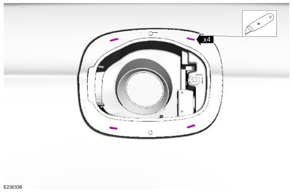
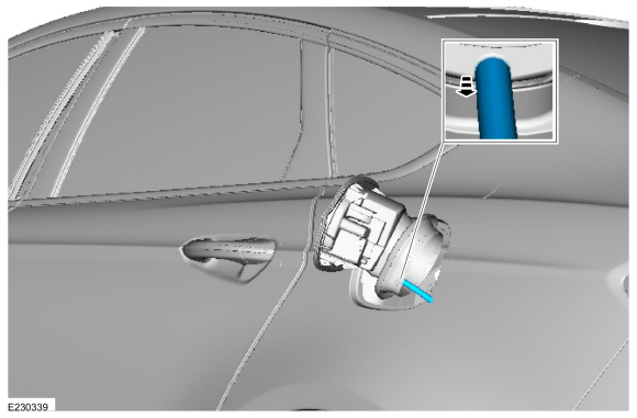
Unseat the fuel filler door assembly boot from inside the wheel opening.
 |
-
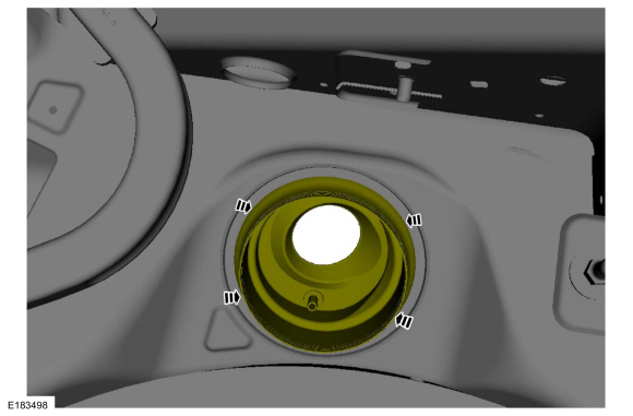
Slice the holes in the indicated areas.
Use the General Equipment: Knife
 |
-
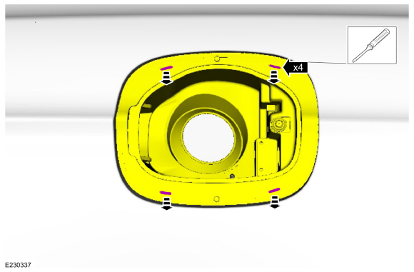
Insert the screwdriver and release the clips while pulling the fuel filler door housing away from the vehicle.
Use the General Equipment: Flat Headed Screw Driver
 |
-
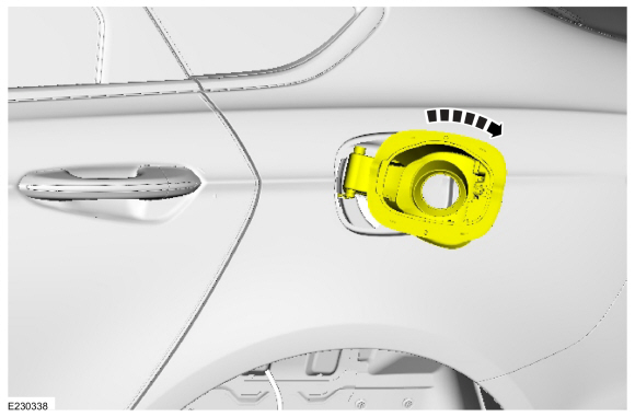
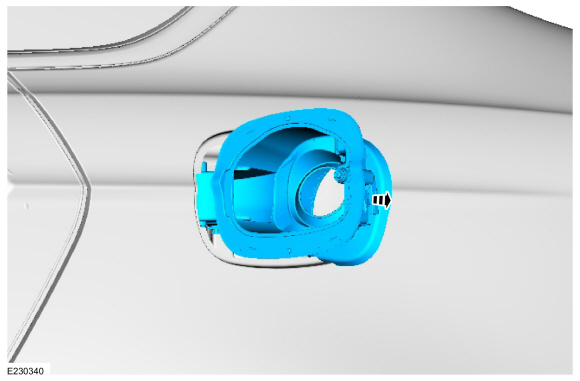
NOTE: Clearance is limited. When all four clips release, the fuel filler door housing can be rotated.
Rotate the fuel filler door housing.
 |
-
Remove the drain tube.
 |
-
Pull the fuel filler door assembly away from the vehicle and remove.
 |
Installation
-
To install, reverse the removal procedure.
 Fuel Filler Door. Removal and Installation
Removal
Open the fuel filler door.
Using a screwdriver, pry the retaining tab back and slide the fuel filler door from the fuel filler door hinge...
 Front Door Check Arm. Removal and Installation
Removal
NOTE:
Left hand (LH) side shown, right hand (RH) side similar.
Remove the front door.
Refer to: Front Door (501-03 Body Closures, Removal and Installation)...
Other information:
Ford Fusion 2013–2020 Service Manual: Luggage Compartment Lid Moulding. Removal and Installation
Special Tool(s) / General Equipment Flat Headed Screw Driver Interior Trim Remover Removal NOTE: Removal steps in this procedure may contain installation details. Position aside the luggage compartment lid pull handle cover...
Ford Fusion 2013–2020 Owners Manual: Normal Scheduled Maintenance
Intelligent Oil-Life Monitor Your vehicle has an Intelligent Oil-Life Monitor that determines when you should change the engine oil based on how you use your vehicle. By using several important factors in its calculations, the monitor helps reduce the cost of owning your vehicle and reduces environmental waste at the same time...
Categories
- Manuals Home
- 2nd Generation Ford Fusion Owners Manual
- 2nd Generation Ford Fusion Service Manual
- Engine - 1.5L EcoBoost (118kW/160PS) – I4
- Traction Control
- Main Control Valve Body. Removal and Installation
- New on site
- Most important about car
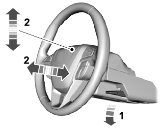
Adjusting the Steering Wheel
WARNING: Do not adjust the steering wheel when your vehicle is moving.
Note: Make sure that you are sitting in the correct position.
Copyright © 2026 www.fofusion2.com