Ford Fusion: Body Closures / Rear Door Alignment. General Procedures
Ford Fusion 2013–2020 Service Manual / Body and Paint / Body and Paint / Body Closures / Rear Door Alignment. General Procedures
Adjustment
NOTE: Removal steps in this procedure may contain installation details.
NOTE: LH shown, RH similar.
All alignments
-
Check the body to rear door dimensions.
Refer to: Body and Frame (501-26 Body Repairs - Vehicle Specific Information and Tolerance Checks, Description and Operation).
-
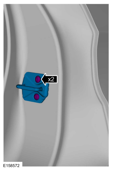
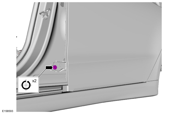
Remove the bolts and the striker assembly.
 |
Rear door in and out, up and down alignment
-
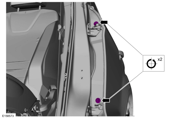
Loosen the bolts to permit movement of the door.
Torque: 35 lb.ft (48 Nm)
 |
-
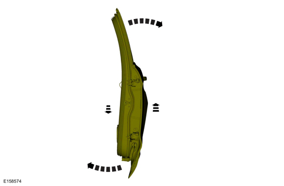
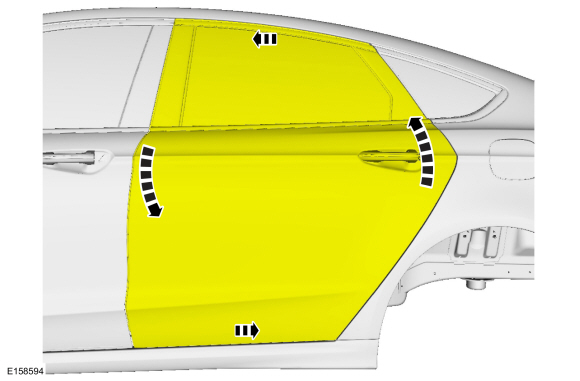
Adjust door to specification.
Refer to: Body and Frame (501-26 Body Repairs - Vehicle Specific Information and Tolerance Checks, Description and Operation).
 |
Rear door fore, aft and tilt alignment
-
Remove the safety belt retractor and pretensioner.
Refer to: Seatbelt Shoulder Height Adjuster (501-20A Seatbelt Systems, Removal and Installation).
-
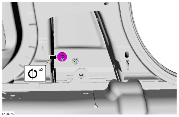
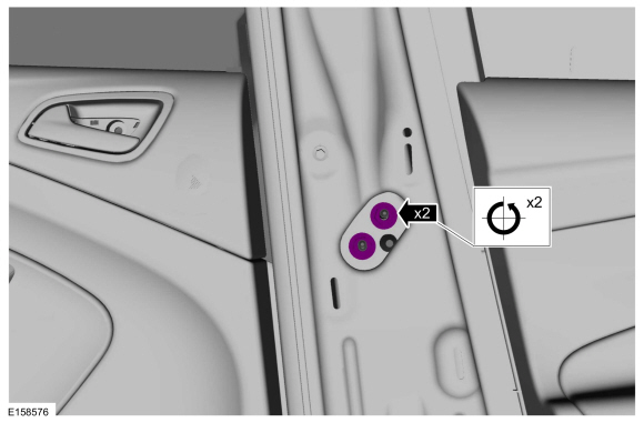
Loosen the nut to permit movement of the door.
Torque: 22 lb.ft (30 Nm)
 |
-
Loosen the bolt to permit movement of the door.
Torque: 22 lb.ft (30 Nm)
 |
-
Loosen the nuts to permit movement of the door.
Torque: 22 lb.ft (30 Nm)
 |
-
Adjust the door to specification.
Refer to: Body and Frame (501-26 Body Repairs - Vehicle Specific Information and Tolerance Checks, Description and Operation).
 |
All alignments
-
Tighten the bolts.
Torque: 18 lb.ft (25 Nm)
 |
-
Check the body to rear door dimensions.
Refer to: Body and Frame (501-26 Body Repairs - Vehicle Specific Information and Tolerance Checks, Description and Operation).
-
Install any removed components as needed.
 Luggage Compartment Lid Alignment. General Procedures
Check
Check the body to luggage compartment lid dimensions.
Refer to: Body and Frame (501-26 Body Repairs - Vehicle Specific Information and Tolerance Checks, Description and Operation)...
 Fuel Filler Door. Removal and Installation
Removal
Open the fuel filler door.
Using a screwdriver, pry the retaining tab back and slide the fuel filler door from the fuel filler door hinge...
Other information:
Ford Fusion 2013–2020 Service Manual: Pinpoint Test - DTC: M. Diagnosis and Testing
B007F:11, B007F:12, B007F:13 and B007F:1A Refer to Wiring Diagrams Cell 46 for schematic and connector information. Normal Operation and Fault Conditions The RCM continuously monitors the passenger seatbelt retractor pretensioner circuits for the following faults: Resistance out of range Unexpected voltage Short to ground Faulted passenger seatbelt retractor p..
Ford Fusion 2013–2020 Owners Manual: Post-Crash Alert System. Transporting the Vehicle
Post-Crash Alert System The system flashes the direction indicators and sounds the horn (intermittently) in the event of a serious impact that deploys an airbag (front, side, side curtain or Safety Canopy) or the seatbelt pretensioners. The horn and indicators turn off when: You press the hazard control button. You press the panic button on the remote entry transmitter (if equipped). You..
Categories
- Manuals Home
- 2nd Generation Ford Fusion Owners Manual
- 2nd Generation Ford Fusion Service Manual
- Body Control Module (BCM). Removal and Installation
- Electronic Parking Brake (EPB) Service Mode Activation and Deactivation. General Procedures
- Powertrain
- New on site
- Most important about car
Using Seatbelts During Pregnancy
WARNING: Always ride and drive with your seatback upright and properly fasten your seatbelt. Fit the lap portion of the seatbelt snugly and low across the hips. Position the shoulder portion of the seatbelt across your chest. Pregnant women must follow this practice. See the following figure.

Copyright © 2026 www.fofusion2.com