
Ford Fusion: Body and Paint / Seatbelt Systems
- Specifications
- Seatbelt Systems - System Operation and Component Description. Description and Operation
- Seatbelt Systems. Diagnosis and Testing
- Locked Seatbelt Retractor Releasing. General Procedures
- Seatbelt Cleaning. General Procedures
- Seatbelt Maintenance. General Procedures
- Seatbelt Procedure After a Collision. General Procedures
- Seatbelt Tongue Rotated On Belt. General Procedures
- Seatbelt Twisted at the Seatbelt Guide. General Procedures
- Front Seatbelt Buckle. Removal and Installation
- Rear Center Seatbelt Retractor. Removal and Installation
- Rear Seatbelt Buckle LH. Removal and Installation
- Rear Seatbelt Buckle RH and Center. Removal and Installation
- Rear Seatbelt Retractor and Pretensioner. Removal and Installation
- Seatbelt Retractor and Pretensioner. Removal and Installation
- Seatbelt Shoulder Height Adjuster. Removal and Installation
 Rear Bumper Cover. Disassembly and Assembly
DISASSEMBLY
NOTE:
Removal steps in this procedure may contain installation details.
Remove the rear bumper cover.
Refer to: Rear Bumper Cover (501-19 Bumpers, Removal and Installation)...
 Specifications
Torque Specifications
Item
Nm
lb-ft
lb-in
Lower Anchors and Tethers for Children (LATCH) bolts
48
35
-
Lower Anchors and Tethers for Children (LATCH) nut
48
35
-
..
Other information:
Ford Fusion 2013–2020 Service Manual: Specifications
General Specifications Item Specification Fuel Pressure Engine running - 1.5L GTDI (Low pressure side) 46.4 –79.8 psi ( 320 –550 kPa) Fuel Tank Capacity 16.50 gal ( 62.45 L) ..
Ford Fusion 2013–2020 Service Manual: Seatbelt Systems. Diagnosis and Testing
Symptom Chart(s) Diagnostics in this manual assume a certain skill level and knowledge of Ford-specific diagnostic practices. REFER to: Diagnostic Methods (100-00 General Information, Description and Operation). Preliminary Inspection Before diagnosing or repairing the seatbelt system, inspect the following items: Seatbelt webbing integrity (torn, frayed, cut or stretched) Seat..
Categories
- Manuals Home
- 2nd Generation Ford Fusion Owners Manual
- 2nd Generation Ford Fusion Service Manual
- Pre-Collision Assist (IF EQUIPPED)
- Under Hood Overview - 1.5L EcoBoost™, 2.0L EcoBoost™, 2.5L, 2.7L EcoBoost™
- Load Carrying
- New on site
- Most important about car
Cross Traffic Alert System Sensors
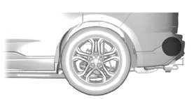
The sensors are behind the rear bumper on both sides of your vehicle.

Copyright © 2026 www.fofusion2.com