Ford Fusion: Automatic Transmission - 6-Speed Automatic Transmission – 6F35 / Main Control Valve Body. Removal and Installation
Removal
-
Remove the main control cover.
Refer to: Main Control Cover - 2.0L EcoBoost (184kW/250PS) – MI4 (307-01A Automatic Transmission - 6-Speed Automatic Transmission – 6F35, Removal and Installation).
Refer to: Main Control Cover - 1.5L EcoBoost (118kW/160PS) – I4 (307-01A Automatic Transmission - 6-Speed Automatic Transmission – 6F35, Removal and Installation).
Refer to: Main Control Cover - 2.5L Duratec (125kW/170PS) (307-01A Automatic Transmission - 6-Speed Automatic Transmission – 6F35, Removal and Installation).
-
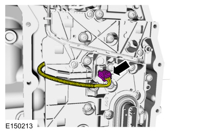
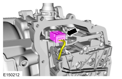
Disconnect the TR sensor electrical connector.
 |
-
Disconnect the OSS sensor electrical connector.
 |
-
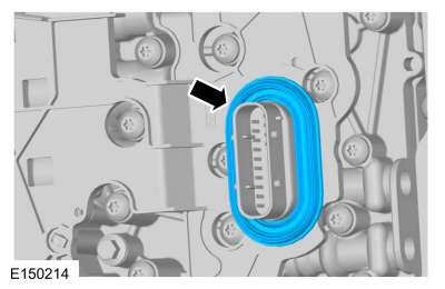
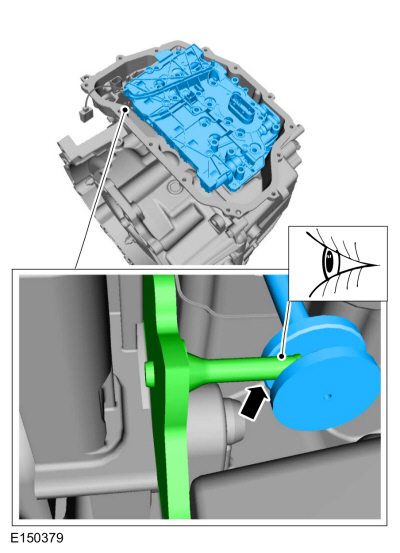
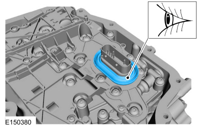
Remove the main control-to-cover seal.
 |
-
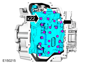
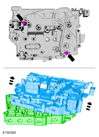
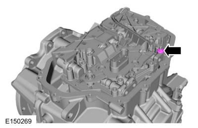
NOTICE: The main control should be handled with care or damage to the main control may occur .
NOTE: Note the location of the short and long main control-to-transmission case bolts for reassembly.
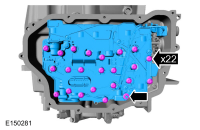
Remove the main control nut, the main control-to-transmission case bolts and the main control.
 |
-
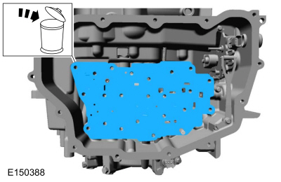
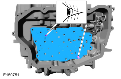
Remove and discard the main control-to-transmission case separator plate.
 |
-
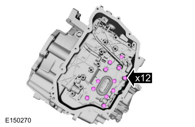
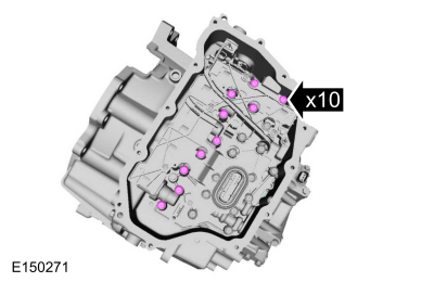
Remove the solenoid body-to-valve body bolts and separate the solenoid body from the main control valve body.
 |
-
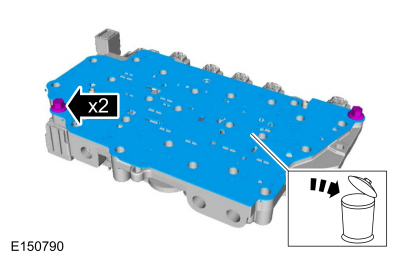
Remove the separator plate-to-solenoid body bolts and remove and discard the separator plate.
 |
Installation
-
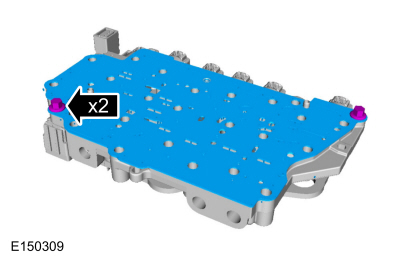
Install the new separator plate and the separator plate-to-solenoid body bolts.
Torque: 89 lb.in (10 Nm)
 |
-
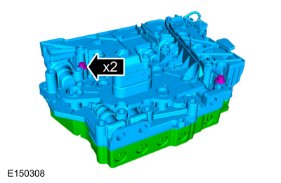
Install the solenoid body onto the main control valve body. Install the solenoid body-to-valve body bolts.
Torque: 89 lb.in (10 Nm)
 |
-
NOTE: Position the OSS and TR sensor wiring harnesses aside.
Install the new main control-to-transmission case separator plate.
 |
-
NOTE: Be sure that the manual lever pin (part of the TR sensor) is correctly installed in the manual valve.
Install the main control assembly.
 |
-
Install the main control nut hand-tight.
 |
-
Install the short main control-to-transmission case bolts hand-tight.
 |
-
Install the long main control-to-transmission case bolts hand-tight.
 |
-
Tighten the main control-to-transmission case bolts and nut in a crisscross pattern.
Torque: 89 lb.in (10 Nm)
 |
-
NOTE: Be sure the main control-to-cover seal is installed with the holes facing up.
Install the main control-to-cover seal.
 |
-
Connect the OSS sensor electrical connector.
 |
-
Connect the TR sensor electrical connector.
 |
-
Install the main control cover.
Refer to: Main Control Cover - 2.0L EcoBoost (184kW/250PS) – MI4 (307-01A Automatic Transmission - 6-Speed Automatic Transmission – 6F35, Removal and Installation).
Refer to: Main Control Cover - 1.5L EcoBoost (118kW/160PS) – I4 (307-01A Automatic Transmission - 6-Speed Automatic Transmission – 6F35, Removal and Installation).
Refer to: Main Control Cover - 2.5L Duratec (125kW/170PS) (307-01A Automatic Transmission - 6-Speed Automatic Transmission – 6F35, Removal and Installation).
-
NOTE: The solenoid body strategy data file and solenoid body identification must be updated anytime a new solenoid body is installed. A new solenoid body service tag must be installed over the current solenoid body service tag on top of the transmission case.
If a new solenoid body is installed, the solenoid body strategy will need to be updated.
Refer to: Transmission Strategy Download (307-01A Automatic Transmission - 6-Speed Automatic Transmission – 6F35, General Procedures).
 Main Control Cover - 2.0L EcoBoost (184kW/250PS) – MI4. Removal and Installation
Materials
Name
Specification
Motorcraft® Ultra Silicone SealantTA-29
WSS-M4G323-A8
Removal
With the vehicle in NEUTRAL, position it on a hoist...
 Output Shaft Speed (OSS) Sensor. Removal and Installation
Removal
Remove the main control valve body.
Refer to: Main Control Valve Body (307-01A Automatic Transmission - 6-Speed Automatic Transmission – 6F35, Removal and Installation)...
Other information:
Ford Fusion 2013–2020 Service Manual: Front Floor Panel Upper Rear Crossmember. Removal and Installation
Special Tool(s) / General Equipment 8 mm Drill Bit MIG/MAG Welding Equipment Spot Weld Drill Bit Locking Pliers Materials Name Specification Seam SealerTA-2-B, 3M™ 08308, LORD Fusor® 803DTM - Removal NOTICE: Battery electric vehicle (BEV), hybrid electric vehicle (HEV) and plug-in hybrid electric vehicle (PHEV) contain a high-voltage battery..
Ford Fusion 2013–2020 Owners Manual: Principle of Operation
WARNING: Always drive and ride with your seatback upright and the lap belt snug and low across the hips. WARNING: Children must always be properly restrained. WARNING: Do not allow a passenger to hold a child on their lap when your vehicle is moving. Failure to follow this instruction could result in personal injury or death in the event of a sudden stop or crash. WARNING: All occupants of..
Categories
- Manuals Home
- 2nd Generation Ford Fusion Owners Manual
- 2nd Generation Ford Fusion Service Manual
- Engine - 1.5L EcoBoost (118kW/160PS) – I4
- Automatic Transmission Fluid Check - 1.5L EcoBoost™/2.0L EcoBoost™/2.5L. Automatic Transmission Fluid Check - 2.7L EcoBoost™
- Memory Function
- New on site
- Most important about car
Fuel Quality
Choosing the Right Fuel
Your vehicle is designed to operate on regular unleaded gasoline with a minimum pump (R+M)/2 octane rating of 87.