Ford Fusion: Automatic Transmission - 6-Speed Automatic Transmission – 6F35 / Main Control Cover - 2.0L EcoBoost (184kW/250PS) – MI4. Removal and Installation
Materials
| Name |
Specification |
Motorcraft® Ultra Silicone Sealant
TA-29 |
WSS-M4G323-A8
|
Removal
-
With the vehicle in NEUTRAL, position it on a hoist.
Refer to: Jacking and Lifting - Overview (100-02 Jacking and Lifting, Description and Operation).
-
Remove the air cleaner assembly.
Refer to: Air Cleaner (303-12B Intake Air Distribution and Filtering - 2.0L EcoBoost (184kW/250PS) – MI4, Removal and Installation).
-
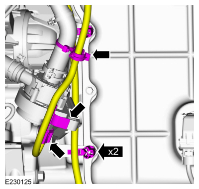
Disconnect the wiring harness retainers and position aside the wiring harness.
-
If equipped, detach the electrical harness retainers.
-
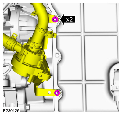
Remove the nuts and position aside the cabin heater coolant pump.
-
Remove the retainers and the front engine undershield.
-
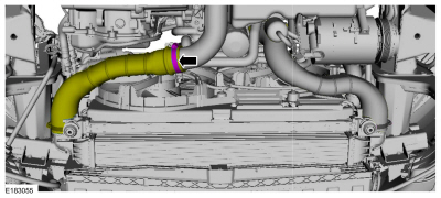
Loosen the clamp and position aside the CAC tube.
-
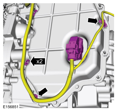
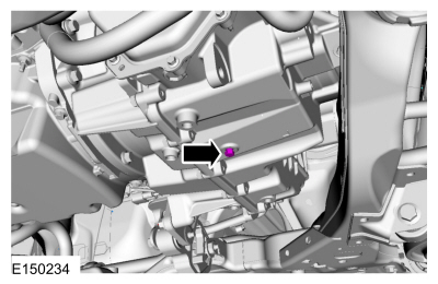
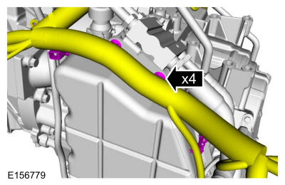
Disconnect the transmission electrical connector and the wiring harness retainers.
-
NOTE:
If an internal problem is suspected, drain the
transmission fluid through a paper filter. A small amount of metal or
friction particles may be found from normal wear. If an excessive amount
of metal or friction material is present, the transmission will need to
be overhauled.
Remove the transmission fluid drain plug and allow the transmission fluid to drain.
-
Install the transmission fluid drain plug when finished.
Torque:
159 lb.in (18 Nm)
-
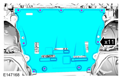
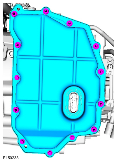
NOTE:
Note the location of the stud bolts for assembly.
Remove the bolts, stud bolts and the main control cover.
Installation
-
NOTICE:
Do not use metal scrapers, wire brushes, power
abrasive discs, or other abrasive means to clean sealing surfaces. These
tools cause scratches and gouges which make leak paths.
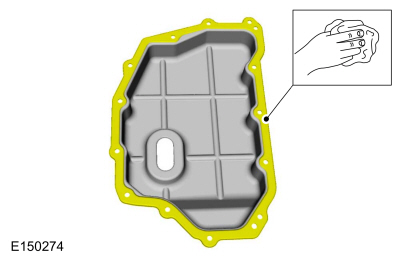
Make sure that the mating faces are clean and free of foreign material.
Refer to: RTV Sealing Surface Cleaning and Preparation (303-00 Engine System - General Information, General Procedures).
-
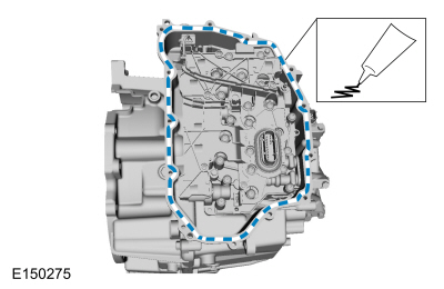
Apply silicone to the main control sealing surface of the transmission case.
Material: Motorcraft® Ultra Silicone Sealant
/ TA-29
(WSS-M4G323-A8)
-
NOTE:
Install the stud bolts in the locations noted during disassembly.
Install the main control cover, the bolts and the stud bolts.
Torque:
106 lb.in (12 Nm)
-
Connect the transmission electrical connector and the wiring harness retainers.
-
Install the CAC tube.
Torque:
44 lb.in (5 Nm)
-
Install the front engine undershield and the retainers.
-
Connect the wiring harness retainers.
-
Install the cabin heater coolant pump and the nuts.
Torque:
80 lb.in (9 Nm)
-
Attach the electrical harness retainers.
-
Install the air cleaner assembly.
Refer to: Air Cleaner (303-12B Intake Air Distribution and Filtering - 2.0L EcoBoost (184kW/250PS) – MI4, Removal and Installation).
-
Fill the transmission with transmission fluid.
Refer to: Transmission Fluid Drain and Refill (307-01A Automatic Transmission - 6-Speed Automatic Transmission – 6F35, General Procedures).
Materials
Name
Specification
Motorcraft® Ultra Silicone SealantTA-29
WSS-M4G323-A8
Motorcraft® MERCON® LV Automatic Transmission FluidXT-10-QLVC
WSS-M2C938-AMERCON® LV,
Removal
With the vehicle in NEUTRAL, position it on a hoist...
Removal
Remove the main control cover.
Refer to: Main Control Cover - 2.0L EcoBoost (184kW/250PS) – MI4 (307-01A Automatic Transmission - 6-Speed Automatic Transmission – 6F35, Removal and Installation)...
Other information:
You can switch this feature on or off and
adjust the settings using the information
display controls.
The climate control system adjusts the
interior temperature during remote start.
You cannot adjust the climate control
setting during remote start operation...
Removal
NOTE:
LH side shown, RH side similar.
NOTE:
Removal steps in this procedure may contain installation details.
All vehicles
Lower the door glass all the way down.
Remove the bolt from the front and the rear of the door moulding and remove the moulding...


 Main Control Cover - 1.5L EcoBoost (118kW/160PS) – I4. Removal and Installation
 Main Control Valve Body. Removal and Installation