Ford Fusion: Supplemental Restraint System / Airbag and Seatbelt Pretensioner Supplemental Restraint System (SRS) - Overview. Description and Operation
Overview
The RCM continually receives and monitors inputs from the OCSM, BECMB and various other hard-wired switches and sensors. If the RCM detects a sudden vehicle deceleration and/or lateral deceleration based on the information received from the various sensors, and determines that deployment is necessary, the RCM applies voltage and current to deploy the appropriate SRS components.
The SRS utilizes Connector Position Assurance (CPA) tabs on deployable component connectors. The tabs disengage the shorting bars of the deployable component from its electrical pins and keep the harness connector securely attached to the deployable component.
If the connector is attached to the deployable component yet the tab is not fully seated, the pins of the connector still make contact with the deployable component pins. However, because the tab is not fully seated and the shorting bars are still applied to the deployable component pins, the RCM detects a fault (circuit resistance below threshold) during self-diagnostics when the vehicle is powered on (airbag warning indicator is illuminated).
 Airbag and Seatbelt Pretensioner Supplemental Restraint System (SRS) - System Operation and Component Description. Description and Operation
System Operation
System Diagram - Supplemental Restraint System (SRS)
SRS Inputs
Item
Description
1
RCM
2
HS-CAN2
3
Passenger Door Side Impact Sensor
4
HS-CAN3
5
HS-CAN1
6
Passenger Seatbelt Buckle Switch
7
Passenger Front Impact Severity Sensor
8
Driver Door Side Impact Sensor
9
Driver C-Pillar Side Impa..
Other information:
Ford Fusion 2013–2020 Service Manual: Oil Pump. Removal and Installation
Special Tool(s) / General Equipment 303-1097Locking Tool, Variable Camshaft Timing Oil Control UnitTKIT-2010B-FLMTKIT-2010B-ROW Materials Name Specification Motorcraft® Metal Brake Parts CleanerPM-4-A, PM-4-B - Removal Remove the crankshaft front seal. Refer to: Crankshaft Front Seal (303-01A Engine - 1.5L EcoBoost (118kW/160PS) – I4, Removal and I..
Ford Fusion 2013–2020 Service Manual: Driver Side Register. Removal and Installation
Special Tool(s) / General Equipment Interior Trim Remover Removal NOTE: Removal steps in this procedure may contain installation details. WARNING: Before beginning any service procedure in this section, refer to Safety Warnings in section 100-00 General Information. Failure to follow this instruction may result in serious personal injury. Refer to: Climate ..
Categories
- Manuals Home
- 2nd Generation Ford Fusion Owners Manual
- 2nd Generation Ford Fusion Service Manual
- Powertrain
- Body Control Module (BCM). Removal and Installation
- Transmission - 1.5L EcoBoost (118kW/160PS) – I4. Removal and Installation
- New on site
- Most important about car
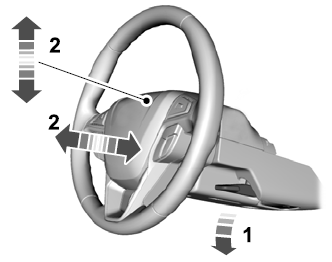
Adjusting the Steering Wheel
WARNING: Do not adjust the steering wheel when your vehicle is moving.
Note: Make sure that you are sitting in the correct position.


