Ford Fusion: Supplemental Restraint System / Airbag and Seatbelt Pretensioner Supplemental Restraint System (SRS) - System Operation and Component Description. Description and Operation
System Operation
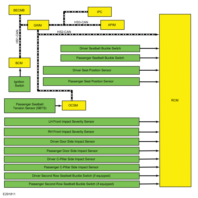
System Diagram - Supplemental Restraint System (SRS)
SRS Inputs
.jpg)
| Item | Description |
|---|---|
| 1 | RCM |
| 2 | HS-CAN2 |
| 3 | Passenger Door Side Impact Sensor |
| 4 | HS-CAN3 |
| 5 | HS-CAN1 |
| 6 | Passenger Seatbelt Buckle Switch |
| 7 | Passenger Front Impact Severity Sensor |
| 8 | Driver Door Side Impact Sensor |
| 9 | Driver C-Pillar Side Impact Sensor |
| 10 | Ignition Switch |
| 11 | Passenger Seatbelt Tension Sensor (SBTS) |
| 12 | GWM |
| 13 | Passenger Seat Position Sensor |
| 14 | Driver Seat Position Sensor |
| 15 | APIM |
| 16 | Passenger C-Pillar Side Impact Sensor |
| 17 | IPC |
| 18 | BCM |
| 19 | Driver Second Row Seatbelt Buckle Switch |
| 20 | Passenger Second Row Seatbelt Buckle Switch |
| 21 | BECMB |
| 22 | Passenger Front Impact Severity Sensor |
| 23 | Driver Seatbelt Buckle Switch |
| 24 | OCSM |
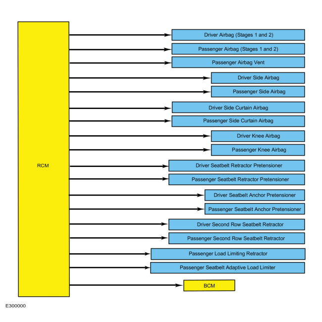
SRS Outputs
.jpg)
| Item | Description |
|---|---|
| 1 | Passenger Seatbelt Anchor Pretensioner |
| 2 | Driver Seatbelt Anchor Pretensioner |
| 3 | Driver Seatbelt Retractor Pretensioner |
| 4 | Passenger Side Curtain Airbag |
| 5 | Driver Side Curtain Airbag |
| 6 | Passenger Side Airbag |
| 7 | Driver Side Airbag |
| 8 | Passenger Airbag (Stages 1 and 2) |
| 9 | Driver Airbag (Stages 1 and 2) |
| 10 | RCM |
| 11 | BCM |
| 12 | Passenger Seatbelt Adaptive Load Limiter |
| 13 | Passenger Seatbelt Retractor Pretensioner |
| 14 | Passenger Load Limiting Retractor |
| 15 | Passenger Airbag Vent |
| 16 | Passenger Knee Airbag |
| 17 | Driver Knee Airbag |
| 18 | Driver Second Row Seatbelt Retractor Pretensioner |
| 19 | Passenger Second Row Seatbelt Retractor Pretensioner |
Network Message Chart - Supplemental Restraint System (SRS)
Module Network Input Messages - RCM
| Broadcast Message | Originating Module | Message Purpose |
|---|---|---|
| eCall confirmation | APIM | Used for SYNC® 911 Assist™ operation. Indicates whether eCall notification is in progress after an airbag deployment. |
| Ignition status | BCM | Used to qualify certain faults during RCM self-diagnostics. |
| Airbag warning indicator status | IPC | Confirms airbag warning indicator status to the RCM. |
| OCS vehicle calibration data | OCSM | Shares application-specific data for comparison purposes to make sure the correct OCSM and RCM are installed. |
| OCS fault status | OCSM | Indicates an OCS fault, if present. |
| OCS sensor data | OCSM | OCS sensor readings. |
| OCS serial number | OCSM | OCSM serial number. |
| Restraints module power status | BECMB | Communicates BECMB fault status to the RCM. |
| Vehicle configuration data | BCM | Used for verifying vehicle configuration data. |
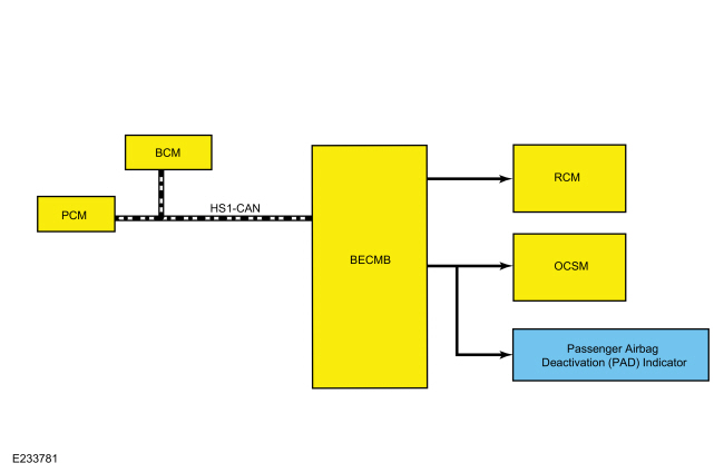
System Diagram - Occupant Classification System (OCS)
.jpg)
| Item | Description |
|---|---|
| 1 | HS-CAN1 |
| 2 | OCSM |
| 3 | RCM |
| 4 | PAD Indicator |
| 5 | BECMB |
| 6 | PCM |
| 7 | BCM |
Network Message Chart - Occupant Classification System (OCS)
Module Network Input Messages
| Broadcast Message | Originating Module | Message Purpose |
|---|---|---|
| Front passenger seatbelt buckle status | RCM | Used for determining passenger airbag disable status. |
| RCM serial number | RCM | RCM serial number. |
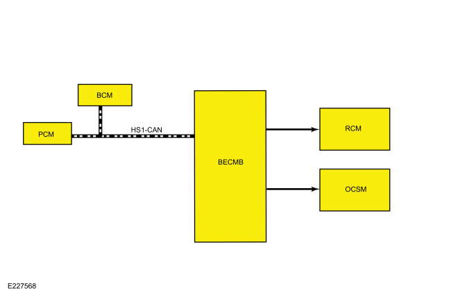
System Diagram - Extended Power Module [BECMB]
.jpg)
| Item | Description |
|---|---|
| 1 | HS-CAN1 |
| 2 | OCSM |
| 3 | RCM |
| 4 | BECM |
| 5 | PCM |
| 6 | BCM |
Network Message Chart - Extended Power Module [BECMB]
Module Network Input Messages - BECMB
| Broadcast Message | Originating Module | Message Purpose |
|---|---|---|
| Ignition status | BCM | Used for determining when it is appropriate to provide power to the SRS. |
| Remote start status | BCM | Used for determining when it is appropriate to provide power to the SRS. |
| Vehicle speed | PCM | Used for determining when it is appropriate to provide power to the SRS. |
Supplemental Restraint System
The SRS is controlled by the RCM, which continually monitors various inputs. When these inputs indicate a frontal or side crash, the RCM may deploy some components, based upon the severity of the crash and the sensor inputs.
Although some deployable devices may not have activated for all occupants during a crash, it does not mean that something is wrong with the SRS.
The RCM performs a self-test of the complete SRS during each startup. In addition to the self-test at start up, the RCM continually monitors all of the SRS components and circuitry for correct operation.
Airbag Warning Indicator
The airbag warning indicator:
- proves out by lighting for 6 seconds and then turning off.
- flashes and/or illuminates based on the message the IPC receives from the RCM.
- illuminates if the IPC does not receive a message from the RCM.
When the ignition is turned ON, the IPC illuminates the airbag warning indicator continuously for 6 seconds. If the SRS is free of faults, the airbag warning indicator turns off and remains off. If a SRS fault exists, the airbag warning indicator illuminates and remains illuminated for the rest of the ignition cycle. The RCM communicates with the IPC via the HS-CAN. The IPC illuminates the airbag warning indicator based on messaging from the RCM. The IPC also illuminates the airbag warning indicator if there is no communication between the RCM and IPC.
Event Notification Signal
The event notification feature provides other vehicle subsystems with information pertaining to SRS deployment or fuel cutoff status. When an impact occurs which exceeds a pre-determined threshold, the RCM sends a signal on a dedicated circuit to the BCM.
When the BCM receives the crash signal input, it initiates fuel cutoff to disable the fuel system.
After the fuel system is disabled, the vehicle can be re-started after carrying out the following steps:
- Turn the ignition on and wait 10 seconds.
- Turn the ignition off.
- Turn the ignition ON.
- Turn the ignition OFF.
- Turn the ignition ON.
Occupant Classification System (OCS)
The OCS classifies the size of the front passenger seat occupant and provides this information to the RCM.
Pressure is applied to the OCS bladder when weight of any occupant or object on the front passenger seat is present. The pressure is then transferred through a tube and sensed by the OCS pressure sensor within the OCSM. The OCSM sends information concerning the weight of any occupant or object on the front passenger seat to the RCM via the HS-CAN2. The RCM uses this information when determining if the passenger airbag or side airbag needs to be deployed in the event of a crash.
The OCS is also used for operation of the passenger Belt-Minder®. For information about Belt-Minder®,
Refer to: Seatbelt Systems - System Operation and Component Description (501-20A Seatbelt Systems, Description and Operation).
afd
To deactivate or reactivate the passenger Belt-Minder® feature,
Refer to: Seatbelt Minder Deactivating/Activating (413-01 Instrumentation, Message Center and Warning Chimes, General Procedures).
Passenger Airbag Deactivation (PAD) Indicator
The RCM controls the PAD indicator through messages sent on the HS-CAN2 and MS-CAN, based on information provided by the OCS. The PAD indicator illuminates to indicate the passenger airbag is disabled.
The RCM briefly activates the PAD indicator during prove out to verify the indicator function and confirm proper functional operation of the PAD indicator to the front occupants.
The following table indicates the passenger airbag and PAD indicator status based on the size of the front passenger occupant.
| Occupant Size | Passenger Seatbelt Buckle Status | Passenger Airbag Status | PAD Indicator Status |
|---|---|---|---|
| Empty | Buckled or Unbuckled | Disabled | OFF: Lit |
| ON: Unlit | |||
| Small | Buckled or Unbuckled | Disabled | OFF: Lit |
| ON: Unlit | |||
| Large | Buckled or Unbuckled | Enabled | OFF: Unlit |
| ON: Lit |
Airbag Second Stage Deployment Check
The
driver and passenger front airbags each have 2 deployment stages. After
an airbag deployment, it is possible that stage 1 has deployed and
stage 2 has not. If a front airbag has deployed, the front airbag must
be remotely deployed using the appropriate airbag disposal procedure to
make sure both stages have been deployed. For information on driver
airbag and/or passenger airbag remote deployment,
Refer to: Pyrotechnic Device Disposal (501-20B Supplemental Restraint System, General Procedures).
SOS Post-Crash Alert System™
The SOS Post-Crash Alert System™ is controlled by the BCM, but initiated by the RCM.
When a deployment or fuel cutoff event occurs, the RCM sends a message on the HS-CAN2 (via the GWM) to the BCM. The BCM flashes the turn signal lamps and sounds the horn (except when 911 Assist™ is active) until it is turned off. The system can be turned off 10 seconds after a crash event by pressing the hazard switch. The BCM also unlocks the doors and illuminates the courtesy lamps after a crash event.
Vehicle Spin-out Detection
When internal RCM sensors detect that the vehicle has spun out, the BCM activates the hazard warning flashers and displays a message in the IPC to indicate the hazard warning flashers are activated due to the spin-out.
Extended Power Module [BECMB]
The BECMB provides system voltage to the RCM and OCSM when the ignition is ON. Additionally, the BECMB is designed to ensure that the RCM and OCSM remain powered on if the ignition is turned off while the vehicle is moving at a speed greater than 4 km/h (2.5 mph).
If the ignition signal is active / high while the vehicle is travelling at a speed above 4 km/h the BECMB maintains system voltage on the RCM and OCSM power supply circuits. If the ignition signal is lost, missing, or below a certain threshold while the vehicle is travelling at a speed above 4 km/h (2.5 mph), the BECMB maintains system voltage on the RCM and OCSM power supply circuits and a telltale appears in the IPC. If the vehicle speed rises above the threshold again, the BECMB does not reactivate the power supply to the RCM and OCSM. They remain off until the ignition is turned on again.
If a vehicle is parked, with the ignition off, the BECMB does not provide power to the RCM and OCSM. If the vehicle begins to move, while the ignition is still off, the BECMB does not power the RCM or OCSM.
When the vehicle has been started using the remote start feature (if equipped), the ignition status is off, but the BECMB powers the RCM in order to detect a collision and disable the fuel pump, if necessary.
Component Description
Front Impact Severity Sensor
The front impact severity sensors measure acceleration (g-rate) and are hardwired to the RCM. Mounting position and orientation is critical for correct operation of the front impact severity sensors.
Occupant Classification System (OCS)
The OCS is found only on the front passenger seat. The OCS classifies the size of the front passenger seat occupant.
The OCS is comprised of a silicone gel-filled bladder mounted between the seat cushion foam and pan, an OCSM which is mounted to the seat frame, and a pressure sensor that is internal to the OCSM. Pressure is applied to the OCS bladder when weight of any occupant or object on the front passenger seat is present. The pressure is then transferred through a tube and sensed by the OCS pressure sensor and OCSM. The components of an OCS bladder system (bladder, tube, and OCSM with integrated pressure sensor) are serviced as an assembly, and the OCS bladder system is serviced as a kit with the seat cushion and seat heater mat (if applicable).
Seatbelt Buckle Sensor
The seatbelt buckles contain integrated sensors that are Hall-effect switches. The seatbelt buckle sensors are serviced with the seatbelt buckle.
On vehicles equipped with rear inflatable seatbelts, the buckle at each rear outboard seating position includes the seatbelt buckle sensor. The rear seatbelt buckle is serviced only as an assembly with the sensor.
Seatbelt Tension Sensor (BTS)
The Seatbelt Tension Sensor (BTS) is a 3-wire Hall-effect sensor that is part of the front passenger seatbelt buckle and cannot be serviced separately from the front passenger seatbelt buckle assembly.
Seat Position Sensor
The seat position sensor is a Hall-effect sensor which indicates the position of the seat along the seat track. The sensor detects the presence of a shunt bracket on the track, indicating the seat has moved past a certain point in the adjustment range.
Side Impact Sensor - Front Door
The front door side impact sensors monitor air pressure within the door in order to detect certain crashes, such as a side impact. They are hardwired to the RCM. Mounting position and orientation is critical for correct operation of the front door side impact sensors.
Side Impact Sensor - C-Pillar
The second row side impact sensors measure acceleration (g-rate), and are hardwired to the RCM. Mounting position and orientation is critical for correct operation of the second row side impact sensors.
Clockspring
The clockspring allows for continuous electrical connections between the driver airbag and the RCM. A spiral-wound cable wraps around the center of the clockspring and as the steering wheel is turned, the spiral cable inside expands or contracts in diameter as the 2 halves of the clockspring turn.
Extended Power Module [BECMB]
The BECMB supplies system voltage to the RCM and OCSM, based on HS-CAN1 inputs and the ignition input.
The BECMB requires PMI when being replaced. Refer to the diagnostic scan tool instructions to carry out PMI.
Deployable Steering Column
The deployable steering column includes a device that, once deployed, reduces the amount of force necessary to collapse the steering column during a crash event. The deployable device is activated by the RCM, depending on the driver seat position and the force of the crash. After deployment, a new steering column must be installed.
Driver Airbag
The driver airbag is a dual-stage airbag. Upon receiving a flow of current, it deploys at 1 of 2 different rates, depending upon vehicle impact severity and sensor input.
Driver Knee Airbag
The driver knee airbag is part of the steering column opening trim panel and deploys upon receiving current flow from the RCM.
Passenger Airbag
The passenger airbag is a dual-stage airbag which deploys at 1 of 2 different rates depending upon vehicle impact severity and sensor input.
Passenger Airbag Canister Vent
The passenger airbag canister vent is a deployable device that is part of the passenger airbag. Canister venting controls the inflation rate of the passenger airbag and the escape rate of gases from the airbag. The canister vent cannot be serviced separately from the passenger airbag.
Passenger Airbag Deactivation (PAD) Indicator
The PAD indicator is a LED which is part of the FCIM. The PAD indicator cannot be serviced separately from the FCIM.
Passenger Knee Airbag
The passenger knee airbag is part of the glove compartment door and deploys upon receiving current flow from the RCM. The passenger knee airbag is only serviced with the glove compartment assembly.
Seatbelt Anchor Pretensioner
The seatbelt anchor pretensioner is a pyrotechnic device that removes excess of webbing slack from the seatbelts when deployed. One is included as part of each front row outboard seatbelt assembly and cannot be serviced separately.
To diagnose any pretensioner Diagnostic Trouble Codes (DTCs),
Refer to: Airbag Supplemental Restraint System (SRS) (501-20B Supplemental Restraint System, Diagnosis and Testing).
Seatbelt Retractor and Adaptive Load Limiter
The front passenger seatbelt retractor is equipped with the adaptive load limiting feature that works in conjunction with the seatbelt buckle pretensioner to control the tension of the front passenger seatbelt in the event of a crash. The front passenger seatbelt retractor is also referred to as the seatbelt load limiter.
To diagnose any pretensioner Diagnostic Trouble Codes (DTCs),
Refer to: Airbag Supplemental Restraint System (SRS) (501-20B Supplemental Restraint System, Diagnosis and Testing).
For any concerns regarding seatbelt retractor function,
Refer to: Seatbelt Systems (501-20A Seatbelt Systems, Diagnosis and Testing).
Seatbelt Retractor Pretensioner
The seatbelt retractor pretensioner is a pyrotechnic device that removes excess of webbing slack from the seatbelts when deployed.
To diagnose any pretensioner Diagnostic Trouble Codes (DTCs),
Refer to: Airbag Supplemental Restraint System (SRS) (501-20B Supplemental Restraint System, Diagnosis and Testing).
For any concerns regarding seatbelt retractor function,
Refer to: Seatbelt Systems (501-20A Seatbelt Systems, Diagnosis and Testing).
Side Air Curtain
The side air curtain is a single-stage airbag which is designed to provide head and upper body protection to the vehicle occupant(s) during certain crashes.
Side Airbag
The side airbag is a single-stage airbag which is designed to provide protection for the seat occupant's torso. It deploys upon receipt of current flow and is attached to the outboard side of each front seat. It is used in conjunction with the side air curtain.
Restraints Control Module (RCM)
NOTE: This vehicle may be equipped with SYNC®, which contains the 911 Assist™ option. Refer to the Owner's Literature for information about this feature.
The RCM monitors various sensor inputs and uses that data for controlling SRS outputs such as the event notification function and airbag deployment.
The RCM includes a backup power supply. This feature provides sufficient backup power to deploy the airbags in the event the ignition circuit is lost or damaged during impact. The backup power supply depletes its stored energy approximately one minute after power and/or ground has been removed from the RCM.
The RCM requires PMI when being replaced. Refer to the diagnostic scan tool instructions to carry out PMI.
 Airbag and Seatbelt Pretensioner Supplemental Restraint System (SRS) - Overview. Description and Operation
Overview
The RCM continually receives and monitors inputs from the OCSM, BECMB and various other hard-wired switches and sensors. If the RCM
detects a sudden vehicle deceleration and/or lateral deceleration based
on the information received from the various sensors, and determines
that deployment is necessary, the RCM applies voltage and current to deploy the appropriate SRS components...
 Airbag Supplemental Restraint System (SRS). Diagnosis and Testing
DTC Chart: Restraint Control Module (RCM)
Diagnostics in this manual assume a certain skill level and knowledge of Ford-specific diagnostic practices...
Other information:
Ford Fusion 2013–2020 Owners Manual: Canceling the Set Speed. Resuming the Set Speed. Automatic Cancellation. Park Brake Application
Canceling the Set Speed Press and release the button or tap the brake pedal. Note: The system remembers the set speed. Resuming the Set Speed Press and release the button. Your vehicle speed returns to the previously set speed and gap setting. The set speed displays continuously in the information display when the system is active...
Ford Fusion 2013–2020 Owners Manual: Recommended Towing Weights
Note: Do not exceed the trailer weight for your vehicle configuration listed in the chart below. Note: Make sure to take into consideration trailer frontal area. Do not exceed 12 feet2 (1.11 meters2) for 1.5L GTDI and 2.5L TiVCT or 20 feet2 (1...
Categories
- Manuals Home
- 2nd Generation Ford Fusion Owners Manual
- 2nd Generation Ford Fusion Service Manual
- Engine
- Powertrain
- Garage Door Opener
- New on site
- Most important about car
Cross Traffic Alert System Sensors
The sensors are behind the rear bumper on both sides of your vehicle.