Ford Fusion: Multifunction Electronic Modules / Body Control Module (BCM). Removal and Installation
Special Tool(s) / General Equipment
| Interior Trim Remover |
Removal
All vehicles
NOTE: Removal steps in this procedure may contain installation details.
-
NOTE: If the BCM did not respond to the diagnostic scan tool, As-Built Data may need to be entered as part of the repair. This step is only necessary if the BCM is being replaced
Using a diagnostic scan tool, begin the PMI process for the BCM following the on-screen instructions.
-
NOTE: The PAM is integral to the BCM. This step is only necessary if the BCM is being replaced.
Using a diagnostic scan tool, begin the PMI process for the PAM following the on-screen instructions.
Vehicles with manual transmission
-
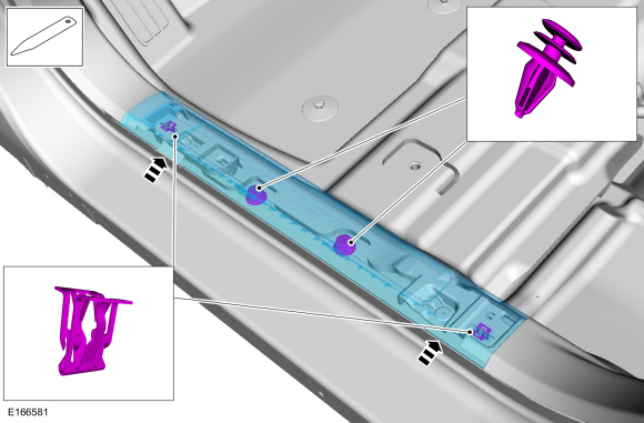
Release the clips, push-pins and remove the LH side front scuff plate.
Use the General Equipment: Interior Trim Remover
 |
-
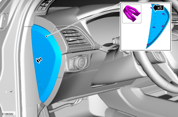
Release the clips and remove the LH instrument panel side trim panel.
 |
-
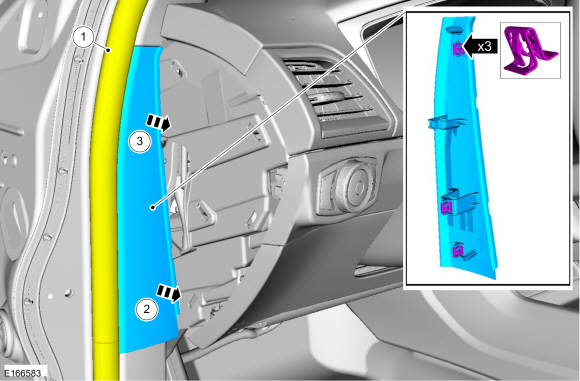
Position the LH front door weatherstrip aside, release the clips and remove the cowl panel upper trim panel.
 |
-
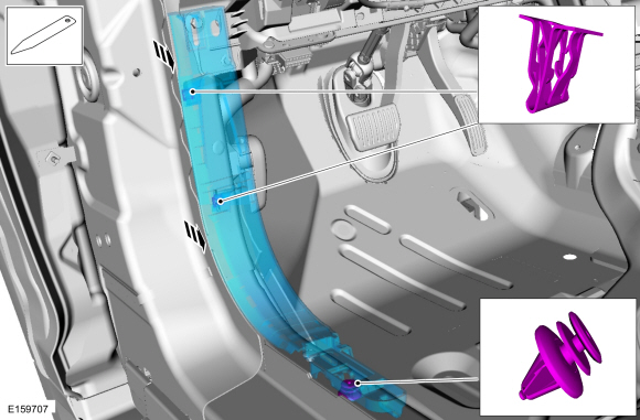
Release the clips, push-pins and remove the LH side lower cowl trim panel.
Use the General Equipment: Interior Trim Remover
 |
-
Remove the push-pins and position the front carpet aside.
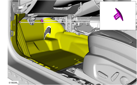 |
-
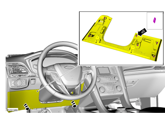
NOTE: Lower for access to electrical connectors.
Release the clips and lower the steering column opening trim panel.
 |
All vehicles
-
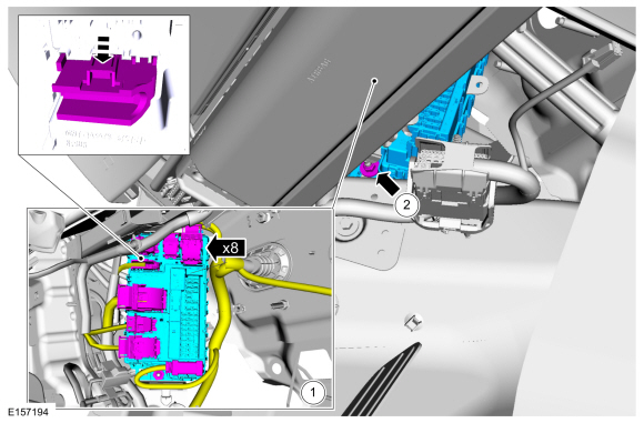
Remove the BCM.
-
Disconnect the electrical connectors.
-
Remove the nut and the BCM.
Torque: 44 lb.in (5 Nm)
-
Disconnect the electrical connectors.
 |
Installation
-
NOTE: If installing a new BCM on vehicles equipped with push button start, the ignition cannot be turned on until 2 keys are programmed to the vehicle. The BCM still communicates with the diagnostic scan tool with the ignition off. If necessary, use the previous diagnostic scan tool session or start a diagnostic scan tool session using the PCM part number or tear tag number located on the PCM.
NOTE: If installing a new BCM, verify at least 2 of the vehicle keys are available prior to carrying out this procedure.
To install, reverse the removal procedure.
NOTE: Carry out the remaining steps only if installing a new BCM.
-
NOTE: A diagnostic scan tool should not be used to program keys for this specific step.
Program the keys.
-
Place the first key in the ignition lock cylinder or the backup starting location.
Refer to: Passive Anti-Theft System (PATS) - Component Location (419-01B Passive Anti-Theft System (PATS), Description and Operation).
-
Turn the ignition lock cylinder to the RUN position
or press the START/STOP button and wait approximately 6 seconds.
-
Turn the ignition lock cylinder to the OFF position or press the START/STOP button and remove the first key.
-
Place the second key in the ignition lock cylinder or the backup starting location.
-
Turn the ignition lock cylinder to the RUN position or press the START/STOP button.
-
Place the first key in the ignition lock cylinder or the backup starting location.
-
Carry out the parameter reset.
Refer to: Anti-Theft Key Programming - Scan Tool (419-01B Passive Anti-Theft System (PATS), General Procedures).
Refer to: Anti-Theft Key Programming - Scan Tool (419-01B Passive Anti-Theft System (PATS), General Procedures).
-
Using a diagnostic scan tool, complete the PMI process for the BCM following the on-screen instructions.
-
Using a diagnostic scan tool, carry out the
Configuration Engine Immobilizer (CEI) configuration following the
on-screen instructions (Toolbox > Body > Service Functions >
CEI Lock Configuration).
-
Using a diagnostic scan tool, carry out the battery
monitor sensor reset following the on-screen instructions (Toolbox >
Body > BMS Reset).
-
NOTE: This step does not apply to vehicles equipped with 360 degree camera view.
If equipped with video rear parking aid, using a diagnostic scan tool, carry out the new module initialization following the on-screen instructions (Toolbox > Electrical > Service Functions > LIN New Module Initialization).
-
Configure the customer preference programmable parameters.
Refer to: Module Configuration - System Operation and Component Description (418-01 Module Configuration, Description and Operation).
-
Train the tire pressure sensors.
Refer to: Tire Pressure Monitoring System (TPMS) Sensor Location Calibration (204-04B Tire Pressure Monitoring System (TPMS), General Procedures).
-
Carry out the BCM self-test (must include an on-demand self-test) and then repeat the self-test to confirm all DTC have been cleared.
-
NOTE: This step applies only to Fusion Energi.
Carry out the PCM Keep Alive Memory (KAM) reset following the scan tool on screen instructions (Toolbox > Powertrain > Reset KAM > PCM).
-
Using a diagnostic scan tool, complete the PMI process for the PAM following the on-screen instructions.
 Transport Mode Deactivation. General Procedures
Deactivation
NOTE:
After vehicle build, some vehicle modules are set in Transport mode including the IPC and the BCM. Transport mode reduces battery drain during longer periods where the vehicle is not used...
 Driver Door Module (DDM). Removal and Installation
Removal
NOTE:
Removal steps in this procedure may contain installation details.
WARNING:
Before beginning any service procedure in this
section, refer to Safety Warnings in section 100-00 General Information...
Other information:
Ford Fusion 2013–2020 Service Manual: Starting System - System Operation and Component Description. Description and Operation
System Operation System Diagram Network Message Chart Module Network Input Messages Powertrain Control Module (PCM) Broadcast Message Originating Module Message Purpose Ignition status BCM Provides the PCM with ignition mode...
Ford Fusion 2013–2020 Service Manual: B-Pillar Outer Panel. Removal and Installation
Special Tool(s) / General Equipment Resistance Spotwelding Equipment Spherical Cutter Hot Air Gun 8 mm Drill Bit MIG/MAG Welding Equipment Spot Weld Drill Bit Locking Pliers Materials Name Specification Metal Bonding AdhesiveTA-1, TA-1-B, 3M™ 08115, LORD Fusor® 108B - Seam SealerTA-2-B, 3M™ 08308, LORD Fusor® 803DTM - ..
Categories
- Manuals Home
- 2nd Generation Ford Fusion Owners Manual
- 2nd Generation Ford Fusion Service Manual
- Main Control Valve Body. Removal and Installation
- Traction Control
- Garage Door Opener
- New on site
- Most important about car
Cross Traffic Alert System Sensors
The sensors are behind the rear bumper on both sides of your vehicle.