Ford Fusion: Seatbelt Systems / Rear Center Seatbelt Retractor. Removal and Installation
Ford Fusion 2013–2020 Service Manual / Body and Paint / Body and Paint / Seatbelt Systems / Rear Center Seatbelt Retractor. Removal and Installation
Removal
NOTE: Removal steps in this procedure may contain installation details.
-
Remove the 60 percent rear seat backrest.
Refer to: Rear Seat Backrest (501-10B Rear Seats, Removal and Installation).
-
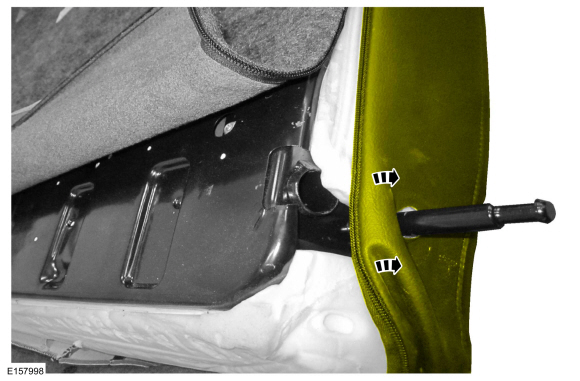
Remove the rear center seatbelt guide bezel.
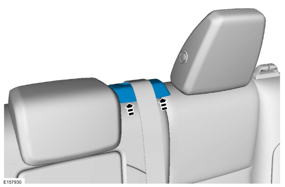 |
-
-
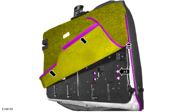
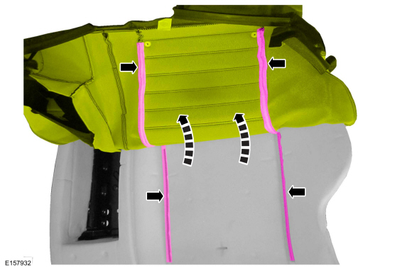
Detach the rear seat J-clips.
-
Unzip and invert the rear seat backrest cover.
-
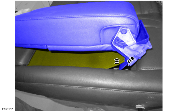
If equipped.
Remove the rear seat armrest bolts.
Torque: 89 lb.in (10 Nm)
-
Detach the rear seat J-clips.
 |
-
If equipped.
Remove the rear seat armrest.
 |
-
If equipped.
Lift the rear seat backrest cover and detach the J-clips.
 |
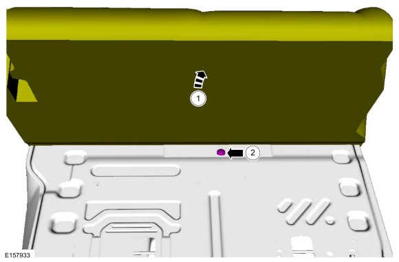
-
Pull the rear seat backrest cover over the rear seat guide pin and position aside.
 |
-
NOTICE: Use care when separating the rear seat backrest cover from the hook-and-loop strips or the hook-and-loop strips may be torn from the rear seat backrest foam.
Release the hook-and-loop strips and invert the rear seat backrest cover.
 |
-
-
Lift the rear seat backrest cover and foam.
-
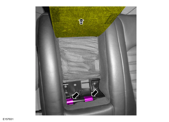
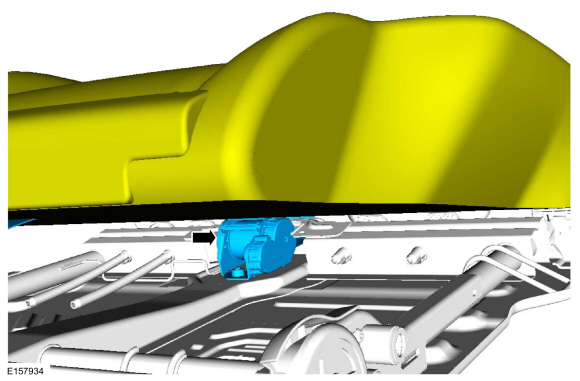
Remove the rear center seatbelt retractor bolt.
Torque: 30 lb.ft (40 Nm)
-
Lift the rear seat backrest cover and foam.
 |
-
Route the rear center seatbelt through the guide.
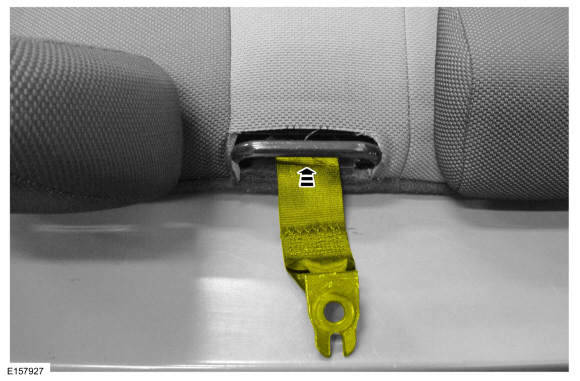 |
-
Remove the rear center seatbelt retractor.
 |
Installation
-
NOTE: During installation, make sure the seatbelt webbing is not twisted and the seatbelts and buckles are accessible to the occupants.
To install, reverse the removal procedure.
-
Check the seatbelt system for correct operation.
Refer to: Seatbelt Systems (501-20A Seatbelt Systems, Diagnosis and Testing).
 Front Seatbelt Buckle. Removal and Installation
Removal
NOTE:
Removal steps in this procedure may contain installation details.
Remove the front seat.
Refer to: Front Seat (501-10A Front Seats, Removal and Installation)...
 Rear Seatbelt Buckle LH. Removal and Installation
Removal
NOTE:
Removal steps in this procedure may contain installation details.
Remove the rear seat cushion.
Refer to: Rear Seat Cushion (501-10B Rear Seats, Removal and Installation)...
Other information:
Ford Fusion 2013–2020 Service Manual: Charging System - Overview. Description and Operation
Overview The generator is driven by the FEAD belt. When the engine is started, the generator begins to generate AC voltage which is internally converted to DC voltage. The DC voltage level is controlled by the voltage regulator (located on the rear of the generator) and is supplied to the battery...
Ford Fusion 2013–2020 Owners Manual: Getting the Services You Need
Warranty repairs to your vehicle must be performed by an authorized dealer. While any authorized dealer handling your vehicle line will provide warranty service, we recommend you return to your selling authorized dealer who wants to ensure your continued satisfaction...
Categories
- Manuals Home
- 2nd Generation Ford Fusion Owners Manual
- 2nd Generation Ford Fusion Service Manual
- Under Hood Overview - 1.5L EcoBoost™, 2.0L EcoBoost™, 2.5L, 2.7L EcoBoost™
- Intake Manifold. Removal and Installation
- Engine - 1.5L EcoBoost (118kW/160PS) – I4
- New on site
- Most important about car
Parallel Parking
The system detects available parallel parking spaces and steers your vehicle into the space. You control the accelerator, gearshift and brakes. The system visually and audibly guides you into a parallel parking space.
 Press the button once to search
for a parking space.
Press the button once to search
for a parking space.
Copyright © 2026 www.fofusion2.com