
Ford Fusion: Body and Paint / Front End Body Panels
- Active Grille Shutter - Overview. Description and Operation
- Active Grille Shutter - System Operation and Component Description. Description and Operation
- Active Grille Shutter. Diagnosis and Testing
- Active Grille Shutter. Removal and Installation
- Active Grille Shutter Actuator. Removal and Installation
- Cowl Panel Grille. Removal and Installation
- Engine Undershield. Removal and Installation
- Engine Front Undershield. Removal and Installation
- Fender. Removal and Installation
- Fender Splash Shield. Removal and Installation
- Hood. Removal and Installation
- Radiator Grille Opening Panel Reinforcement. Removal and Installation
 Body System. Diagnosis and Testing
Symptom Chart(s)
Diagnostics in this manual assume a certain skill level and knowledge of Ford-specific diagnostic practices. REFER to: Diagnostic Methods (100-00 General Information, Description and Operation)...
 Active Grille Shutter - Overview. Description and Operation
Overview
The
active grille shutter system (if equipped) is comprised of the grille
shutter assembly and the grille shutter actuator. The active grille
shutter system is primarily used to maximize fuel economy by reducing
aerodynamic drag on the vehicle...
Other information:
Ford Fusion 2013–2020 Service Manual: Steering Wheel and Column Electrical Components - Overview. Description and Operation
Steering Column Switches Overview The steering column switches are located on and around the steering column. This enables the driver to control various vehicle functions and remain focused on driving. Depending on vehicle options, the steering column switches consist of: Multifunction switch - mounted on the left side of the SCCM and can be serviced separately...
Ford Fusion 2013–2020 Owners Manual: Refueling System Overview
Fuel filler door. Fuel tank filler valve. Fuel tank filler pipe. Your vehicle does not have a fuel tank filler cap. Left-hand side. To open the fuel filler door, press the center rear edge of the fuel filler door and then release. Right-hand side...
Categories
- Manuals Home
- 2nd Generation Ford Fusion Owners Manual
- 2nd Generation Ford Fusion Service Manual
- Load Carrying
- Cylinder Head. Removal and Installation
- Starter Motor. Removal and Installation
- New on site
- Most important about car
Cross Traffic Alert System Sensors
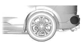
The sensors are behind the rear bumper on both sides of your vehicle.

Copyright © 2026 www.fofusion2.com