Ford Fusion: Starting System - 1.5L EcoBoost (118kW/160PS) – I4 / Starting System - System Operation and Component Description. Description and Operation
System Operation
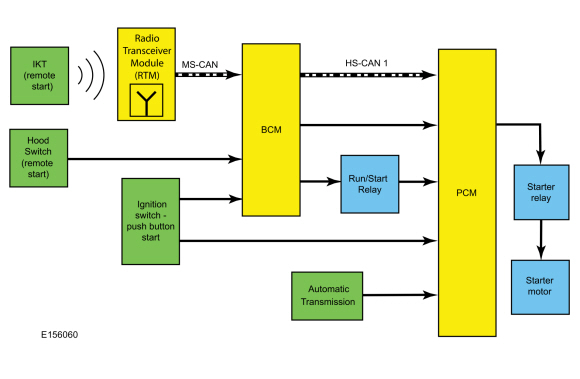
System Diagram
Network Message Chart
Module Network Input Messages Powertrain Control Module (PCM)
| Broadcast Message | Originating Module | Message Purpose |
|---|---|---|
| Ignition status | BCM | Provides the PCM with ignition mode. |
Starting System
This vehicle is equipped with a PATS that disables the engine from starting if an unprogrammed PATS key is used or an invalid PCM ID is received. The PATS is controlled by the BCM. If there is a PATS concern that disables the engine, the IPC displays the corresponding message in the message center.
Refer to: Passive Anti-Theft System (PATS) - System Operation and Component Description (419-01B Passive Anti-Theft System (PATS), Description and Operation).
The starting system controls the cranking of the engine. Ignition modes are controlled by the BCM. For more information on push-button start
Refer to: Steering Wheel and Column Electrical Components - System Operation and Component Description (211-05 Steering Wheel and Column Electrical Components, Description and Operation).
The ignition switch - push button start is connected to the BCM and the PCM in case of a failure. If there is a circuit failure to either module from the ignition switch - push button start, the modules communicate the ignition switch - push button start request to each other over the High Speed Controller Area Network (HS-CAN). During a start event, the ignition switch - push button start is pressed in combination with the brake pedal. The BCM and the PCM receive a request to start the engine. The PCM recognizes the correct inputs and provides voltage and ground to energize the starter relay coil and close the starter relay contacts. The starter relay contacts close, providing voltage to the starter solenoid, allowing the starter motor to crank the engine. The PCM disengages the starter motor once an engine Revolutions Per Minute (RPM) threshold is reached, a set crank time is exceeded or the ignition switch - push button start is pressed indicating an engine shutdown request.
Remote Start
The remote start system is controlled by the RKE system. For more information,
Refer to: Handles, Locks, Latches and Entry Systems - System Operation and Component Description (501-14 Handles, Locks, Latches and Entry Systems, Description and Operation).
Auto-start-stop System
The Auto-Start-Stop system helps reduce fuel consumption by automatically shutting off the vehicle’s engine while the vehicle is stopped and restarting the engine when you release the brake pedal. The Auto-Start-Stop system is automatically enabled whenever the ignition is turned on. If necessary, the system can be disabled through the IPC message center.
Reasons the engine may automatically restart :
- The brake pedal is released.
- The Auto-start-stop system is disabled through the IPC message center.
- The battery has a low state of charge.
- To maintain interior comfort.
- The blower fan speed is increased or the climate control temperature is changed.
- An electrical accessory is turned ON or plugged in.
- Low brake vacuum.
The system may not turn the engine off under these conditions:
- The HVAC system is in A/C, heat or defrost modes.
- The rear defroster is ON.
- The battery has a low state of charge.
- The battery temperature is below 5°C (41°F) or above 60°C (140°F).
- The engine temperature is below 60°C (140°F).
- The gear selector is not in Drive.
- The steering wheel is turned rapidly or is at a sharp angle.
- Vehicle speed of greater than 4 km/h (2.5 mph) for more than 2 seconds has not occurred.
- The vehicle is on a steep road grade.
- Elevation is approximately above 10,000 feet (3,048 meters).
For more information refer to the Owner's Literature and Refer to Powertrain Control/Emissions Diagnosis (PC/ED) manual.
Component Description
Body Control Module (BCM)
Refer to: Module Controlled Functions - System Operation and Component Description (419-10 Multifunction Electronic Modules, Description and Operation).
Ignition Switch - Push Button Start
The ignition switch - push button start (Engine Start/Stop button) is a momentary contact switch that is hardwired to the BCM and the PCM. The ignition switch - push button start is used to obtain the OFF, ON or START ignition modes. For more information,
Refer to: Steering Wheel and Column Electrical Components - System Operation and Component Description (211-05 Steering Wheel and Column Electrical Components, Description and Operation).
Passive Key
Refer to: Passive Anti-Theft System (PATS) - System Operation and Component Description (419-01B Passive Anti-Theft System (PATS), Description and Operation).
Passive Anti-Theft Transceiver
Refer to: Passive Anti-Theft System (PATS) - System Operation and Component Description (419-01B Passive Anti-Theft System (PATS), Description and Operation).
Powertrain Control Module (PCM)
The PCM provides power and ground to the starter relay to initiate cranking of the engine.
RTM
Refer to: Tire Pressure Monitoring System (TPMS) - System Operation and Component Description (204-04B Tire Pressure Monitoring System (TPMS), Description and Operation).
 Starting System - Overview. Description and Operation
The
starting system controls the cranking of the engine. The starter motor
is enabled by the starter relay when the relay is activated by the PCM. The PCM receives inputs from the ignition switch - push button start, automatic transmission, Run/start relay and the BCM before activating the starter relay to initiate cranking of the engine...
 Starting System. Diagnosis and Testing
Inspection and Verification
Diagnostics in this manual assume a certain skill level and knowledge of Ford-specific diagnostic practices. REFER to: Diagnostic Methods (100-00 General Information, Description and Operation)...
Other information:
Ford Fusion 2013–2020 Service Manual: Turbocharger - Overview. Description and Operation
Overview NOTICE: Whenever turbocharger air intake system components are removed, always cover open ports to protect from debris. It is important that no foreign material enter the system. The turbocharger compressor vanes are susceptible to damage from even small particles...
Ford Fusion 2013–2020 Service Manual: Blind Spot Information System - Component Location. Description and Operation
Component Location - BLIS®/ CTA Item Description 1 Exterior mirrors 2 PDM 3 SODL and SODR 4 DDM ..
Categories
- Manuals Home
- 2nd Generation Ford Fusion Owners Manual
- 2nd Generation Ford Fusion Service Manual
- Traction Control
- Transmission - 1.5L EcoBoost (118kW/160PS) – I4. Removal and Installation
- Under Hood Overview - 1.5L EcoBoost™, 2.0L EcoBoost™, 2.5L, 2.7L EcoBoost™
- New on site
- Most important about car
Cross Traffic Alert System Sensors
The sensors are behind the rear bumper on both sides of your vehicle.