Ford Fusion: Starting System - 1.5L EcoBoost (118kW/160PS) – I4 / Starting System. Diagnosis and Testing
Inspection and Verification
Diagnostics in this manual assume a certain skill level and knowledge of Ford-specific diagnostic practices.
REFER to: Diagnostic Methods (100-00 General Information, Description and Operation).
-
Verify the customer concern.
-
Check the battery for loose, damaged or corroded connections.
-
Check the battery condition and state of charge.
REFER to: Battery (414-01 Battery, Mounting and Cables, Diagnosis and Testing).
-
Remove the accessory drive belt.
REFER to: Accessory Drive Belt (303-05A Accessory Drive - 1.5L EcoBoost (118kW/160PS) – I4, Removal and Installation).
Verify the crankshaft and each of the components driven by the accessory drive belt rotate and are not seized or damaged.
-
If any aftermarket accessories have been added to the vehicle, make sure they are properly wired.
-
If an obvious cause for an observed or reported concern is found, correct the cause (if possible) before proceeding.
-
Using the diagnostic scan tool, retrieve all Diagnostic
Trouble Codes (DTCs). Refer to the appropriate DTC Chart in this
section.
DTC Charts
Diagnostics in this manual assume a certain skill level and knowledge of Ford-specific diagnostic practices.
REFER to: Diagnostic Methods (100-00 General Information, Description and Operation).
BCM DTC Chart
| DTC | Description | Action |
|---|---|---|
| C113A:11 | PCM Wake-up Signal: Circuit Short to Ground | GO to Pinpoint Test C |
| C113A:15 | PCM Wake-up Signal: Circuit Short to Battery or Open | GO to Pinpoint Test C |
| All Other DTCs | - |
REFER to: Body Control Module (BCM) (419-10 Multifunction Electronic Modules, Removal and Installation). |
PCM DTC Chart
| DTC | Description | Action |
|---|---|---|
| P06E4 | Control Module Wake-up Circuit Performance |
RETRIEVE and RECORD all CMDTCs. If BCM
DTC C113A:11 or C113A:15 is found, GO to Pinpoint Test C Clear all Diagnostic Trouble Codes (DTCs). RERUN the PCM self-test. If the DTC returns, CHECK OASIS
for any applicable Technical Service Bulletins (TSBs). If no Technical
Service Bulletins (TSBs) address this concern,
 Click here to access Guided Routine (PCM).
 Internet Explorer version 11 or greater is required to perform this Pinpoint Test. Internet Explorer version 11 or greater is required to perform this Pinpoint Test. |
| P06E9 | Engine Starter Performance | If the engine cranks, Refer to Powertrain Control/Emissions Diagnosis (PC/ED) manual. If the engine does not crank, GO to Pinpoint Test A |
| P0706 | Transmission Range Sensor "A" Circuit Range/Performance |
REFER to: Automatic Transmission - 1.5L EcoBoost (118kW/160PS) – I4 (307-01A Automatic Transmission - 6-Speed Automatic Transmission – 6F35, Diagnosis and Testing). |
| P0707 | Transmission Range Sensor "A" Circuit Low |
REFER to: Automatic Transmission - 1.5L EcoBoost (118kW/160PS) – I4 (307-01A Automatic Transmission - 6-Speed Automatic Transmission – 6F35, Diagnosis and Testing). |
| P0708 | Transmission Range Sensor "A" Circuit High |
REFER to: Automatic Transmission - 1.5L EcoBoost (118kW/160PS) – I4 (307-01A Automatic Transmission - 6-Speed Automatic Transmission – 6F35, Diagnosis and Testing). |
| P162F | Starter Motor Disabled - Engine Crank Time Too Long | This DTC sets in the PCM when the engine has been cranked for more than a total of 60 seconds without allowing sufficient time for the starter to cool. Diagnose all other DTCs and symptoms. Check the charging system voltage and correct as necessary. Clear the DTC. |
| P2534 | Ignition Switch Run/Start Position Circuit Low | GO to Pinpoint Test D |
| P2535 | Ignition Switch Run/Start Position Circuit High | GO to Pinpoint Test D |
| All Other DTCs | - |
RTM DTC Chart
| DTC | Description | Action |
|---|---|---|
| All DTCs | - |
REFER to: Tire Pressure Monitoring System (TPMS) (204-04B Tire Pressure Monitoring System (TPMS), Diagnosis and Testing). |
Symptom Chart(s)
Symptom Chart: Starting System
Diagnostics in this manual assume a certain skill level and knowledge of Ford-specific diagnostic practices.
REFER to: Diagnostic Methods (100-00 General Information, Description and Operation).
Symptom Chart
| Condition | Possible Sources | Actions |
|---|---|---|
| The engine does not crank | Refer to the Pinpoint Test. | GO to Pinpoint Test A |
| The engine cranks slowly | Refer to the Pinpoint Test. | PERFORM the starter system component test. REFER to Starter Motor - Positive Circuit Test in this section. |
| The engine cranks but will not start |
|
Refer to Powertrain Control/Emissions Diagnosis (PC/ED) manual. |
| Unusual starter noise | Refer to the Pinpoint Test. | GO to Pinpoint Test B |
| The starter spins but the engine does not crank | Starter motor | INSPECT the starter motor mounting and engagement. REPAIR as necessary. |
| Damaged flexplate | INSPECT the flexplate for damaged, missing or worn teeth. REPAIR as necessary. | |
| The starter does not disengage from the flexplate |
|
REMOVE the starter relay. If the engine stops cranking, INSTALL a new relay. If the engine continues to crank, REPAIR circuit CDC35 (BU/WH) for a short to voltage. |
| The remote start is inoperative |
|
REFER to: Locks, Latches and Entry Systems (501-14 Handles, Locks, Latches and Entry Systems, Diagnosis and Testing). |
| The remote start has poor range performance |
|
Diagnose The RKE Transmitter Has Poor Range Performance, REFER to: Locks, Latches and Entry Systems (501-14 Handles, Locks, Latches and Entry Systems, Diagnosis and Testing). |
Symptom Chart: Auto-Start-Stop System
Diagnostics in this manual assume a certain skill level and knowledge of Ford-specific diagnostic practices.
REFER to: Diagnostic Methods (100-00 General Information, Description and Operation).
Symptom Chart
| Condition | Possible Sources | Actions |
|---|---|---|
| Auto-Start-Stop System is inoperative or does not operate correctly | One or more required criteria required for Auto-start-stop operation has not been met. | REFER to owners manual and Refer to Powertrain Control/Emissions Diagnosis (PC/ED) manual. for proper system operation. |
| Electronic Control Modules |
|
|
| Vehicle Battery | Refer to Powertrain Control/Emissions Diagnosis (PC/ED) manual. Section 3 Symptom Charts. | |
| Auto-Start-Stop System cannot be disabled by driver |
|
|
Pinpoint Test(s)
Engine Does Not Crank
Refer to Wiring Diagrams Cell 20 for schematic and connector information.
Normal Operation and Fault Conditions
REFER to: Starting System - System Operation and Component Description (303-06A Starting System - 1.5L EcoBoost (118kW/160PS) – I4, Description and Operation).
DTC Fault Trigger Conditions
| DTC | Description | Fault Trigger Conditions |
|---|---|---|
| P06E9 | Engine Starter Performance | No engine rotation detected during crank event |
Possible Sources
- Battery
- Battery cables
- IPC
- Starter motor
- BJB starter relay
Visual Inspection and Diagnostic Pre-checks
- Inspect the Run/start relay.
- Inspect the high current BJB connections.
- Verify the BJB fuse 84 (10A).
- Verify the BCM fuse 12 (7.5A).
- Inspect the Integrated Keyhead Transmitter (IKT).
PINPOINT TEST A : ENGINE DOES NOT CRANK
| A1 PERFORM INSPECTION AND VERIFICATION | |||||||||||||
Was an obvious cause for an observed or reported concern found?
|
|||||||||||||
| A2 CHECK FOR NO KEY DETECTED MESSAGE IN THE MESSAGE CENTER | |||||||||||||
Is NO KEY DETECTED displayed?
|
|||||||||||||
| A3 VERIFY THE BCM (BODY CONTROL MODULE) , IPC (INSTRUMENT PANEL CLUSTER) AND PCM (POWERTRAIN CONTROL MODULE) PASS THE NETWORK TEST | |||||||||||||
Did the BCM, IPC and PCM pass the Network Test?
|
|||||||||||||
| A4 RETRIEVE DIAGNOSTIC TROUBLE CODES (DTCS) | |||||||||||||
Are any Diagnostic Trouble Codes (DTCs) present?
|
|||||||||||||
| A5 CHECK THE OPERATION OF THE STOPLAMPS | |||||||||||||
Do the stoplamps illuminate?
|
|||||||||||||
| A6 CHECK THE BRAKE PEDAL POSITION (BOO1) PID (PARAMETER IDENTIFICATION) | |||||||||||||
Does the PID read On?
|
|||||||||||||
| A7 CHECK THE BPP (BRAKE PEDAL POSITION) SWITCH CIRCUIT FOR VOLTAGE AT THE PCM | |||||||||||||
Is the voltage greater than 11 volts?
|
|||||||||||||
| A8 CHECK BCM (BODY CONTROL MODULE) IGN_SW_STATE PID (PARAMETER IDENTIFICATION) | |||||||||||||
Does the PID change from Off to Start when the ignition switch - push button start and the brake pedal are pressed?
|
|||||||||||||
| A9 CHECK THE PCM (POWERTRAIN CONTROL MODULE) IN GEAR-TRANSMISSION IS APPLYING A LOAD TO ENGINE (IN_GEAR) PID (PARAMETER IDENTIFICATION) | |||||||||||||
Does the PID read No in both positions?
|
|||||||||||||
| A10 CHECK THE PCM (POWERTRAIN CONTROL MODULE) ENGINE CRANKING (ENG_CRANK) PID (PARAMETER IDENTIFICATION) | |||||||||||||
Does the PID change from Inactive to Active?
|
|||||||||||||
| A11 CHECK THE STARTER RELAY CONTROL OPERATION | |||||||||||||
|
NOTICE: The following step uses a test light to simulate normal circuit loads. Use only the test light recommended in the Special Tools table at the beginning of this section. To avoid connector terminal damage, use the Flex Probe Kit for the test light probe connection to the vehicle. Do not use the test light probe directly on any connector.
Does the test light illuminate when the ignition switch - push button start is pressed?
|
|||||||||||||
| A12 CHECK THE VOLTAGE TO THE STARTER RELAY | |||||||||||||
Is the voltage greater than 11 volts?
|
|||||||||||||
| A13 CHECK THE STARTER MOTOR OPERATION AT THE STARTER RELAY | |||||||||||||
Did the starter engage and the engine crank?
|
|||||||||||||
| A14 CHECK THE BATTERY GROUND CABLES | |||||||||||||
Are the voltages greater than 11 volts?
|
|||||||||||||
| A15 CHECK THE STARTER MOTOR GROUND | |||||||||||||
Is the voltage greater than 11 volts?
|
|||||||||||||
| A16 CHECK THE VOLTAGE TO THE STARTER MOTOR | |||||||||||||
Is the voltage greater than 11 volts?
|
|||||||||||||
| A17 CHECK THE STARTER MOTOR FOR CORRECT OPERATION | |||||||||||||
Was an obvious cause found?
|
|||||||||||||
| A18 CHECK FOR START INPUT AT THE STARTER | |||||||||||||
Is the voltage greater than 11 volts?
|
|||||||||||||
| A19 CHECK THE PCM (POWERTRAIN CONTROL MODULE) STARTER RELAY CIRCUITS FOR A SHORT TO GROUND | |||||||||||||
Are the resistances greater than 10,000 ohms?
|
|||||||||||||
| A20 CHECK THE PCM (POWERTRAIN CONTROL MODULE) STARTER RELAY CIRCUITS FOR AN OPEN | |||||||||||||
Are the resistances less than 3 ohms?
|
|||||||||||||
| A21 CHECK FOR CORRECT PCM (POWERTRAIN CONTROL MODULE) OPERATION | |||||||||||||
Is the concern still present?
|

 BJB starter relay pin 1

 BJB starter relay pin 2
 BJB starter relay pin 3

 BJB starter relay pin 3

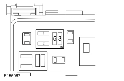 BJB starter relay pin 5


 Starter motor case


 Click here to access Guided Routine (PCM).
 Internet Explorer version 11 or greater is required to perform this Pinpoint Test.
Unusual Starter Noise
Normal Operation and Fault Conditions
Correct starter operation relies on correct mounting of the starter to the engine, alignment of the starter ring gear to the flexplate and correct functioning of the starter assembly (internal gears, bearings).
Possible Sources
- Engine
- Starter motor
- Starter motor mounting
Visual Inspection and Diagnostic Pre-checks
- Inspect the starter motor.
- Inspect the starter motor mounting.
PINPOINT TEST B : UNUSUAL STARTER NOISE
| B1 CHECK THE STARTER MOUNTING | ||||
Is the starter motor mounted correctly?
|
||||
| B2 CHECK FOR STARTER NOISE | ||||
Is the noise due to the starter engagement?
|
C113A:11 or C113A:15
Refer to Wiring Diagrams Cell 23 for schematic and connector information.
Normal Operation and Fault Conditions
The wake-up control circuit wakes up the PCM prior to the engine cranking. The PCM needs to wake up prior to a crank request so it has time to go through its initialization. The wake-up control circuit is controlled by the BCM. The BCM activates the wake-up control circuit when the driver door is opened, a key is inserted into the ignition, or when the ignition is in the ON or START position.
DTC Fault Trigger Conditions
| DTC | Description | Fault Trigger Conditions |
|---|---|---|
| C113A:11 | PCM Wake-up Signal: Circuit Short to Ground | Set by the BCM when a short to ground is detected on the wake-up control circuit. |
| C113A:15 | PCM Wake-up Signal: Circuit Short to Battery or Open | Set by the BCM when a short to voltage or an open is detected on the wake-up control circuit. |
Possible Sources
- BCM
- PCM
- Wiring, terminals or connectors
PINPOINT TEST C : C113A:11 OR C113A:15
| C1 CHECK FOR BCM (BODY CONTROL MODULE) DTCS | ||||||||||
Is DTC C113A:11 present?
|
||||||||||
| C2 CHECK THE PCM (POWERTRAIN CONTROL MODULE) FOR A SHORT TO GROUND | ||||||||||
Is BCM DTC C113A:11 present?
|
||||||||||
| C3 CHECK THE PCM (POWERTRAIN CONTROL MODULE) WAKE-UP SIGNAL CIRCUIT FOR A SHORT TO GROUND | ||||||||||
Is the resistance greater than 10,000 ohms?
|
||||||||||
| C4 CHECK THE PCM (POWERTRAIN CONTROL MODULE) WAKE-UP SIGNAL CIRCUIT FOR A SHORT TO VOLTAGE | ||||||||||
Is any voltage present?
|
||||||||||
| C5 CHECK THE PCM (POWERTRAIN CONTROL MODULE) WAKE-UP SIGNAL CIRCUIT FOR AN OPEN | ||||||||||
Is the resistance less than 3 ohms?
|
||||||||||
| C6 CHECK FOR CORRECT BCM (BODY CONTROL MODULE) OPERATION | ||||||||||
Is the concern still present?
|
||||||||||
| C7 CHECK FOR CORRECT PCM (POWERTRAIN CONTROL MODULE) OPERATION | ||||||||||
Is the concern still present?
|


 Click here to access Guided Routine (BCM).
 Internet Explorer version 11 or greater is required to perform this Pinpoint Test.
 Click here to access Guided Routine (PCM).
 Internet Explorer version 11 or greater is required to perform this Pinpoint Test.
P2534 or P2535
Refer to Wiring Diagrams Cell 20 for schematic and connector information.
Normal Operation and Fault Conditions
When the engine start/stop switch has been pressed, the PCM receives a voltage signal on the crank detect circuit. The PCM then supplies voltage and ground to the starter relay coil when the required inputs have been received.
DTC Fault Trigger Conditions
| DTC | Description | Fault Trigger Conditions |
|---|---|---|
| P2534 | Ignition Switch Run/Start Position Circuit Low | This DTC sets when the PCM or BCM detects low voltage on the crank detect circuit while the engine is running. |
| P2535 | Ignition Switch Run/Start Position Circuit High | This DTC sets when the PCM detects a short to voltage on the crank detect circuit while the engine is running. |
Possible Sources
- BCM
- Ignition switch - Push Button Start
- PCM
- Wiring, terminals or connectors
PINPOINT TEST D : DTC P2534 OR P2535
| D1 RETRIEVE DIAGNOSTIC TROUBLE CODES (DTCS) | ||||||||||
Is DTC P2534 or P2535 recorded?
|
||||||||||
| D2 CHECK THE CRANK DETECT CIRCUIT FOR A SHORT TO VOLTAGE WITH PCM (POWERTRAIN CONTROL MODULE) DISCONNECTED | ||||||||||
Is any voltage present?
|
||||||||||
| D3 CHECK THE CRANK DETECT CIRCUIT FOR A SHORT TO VOLTAGE WITH IGNITION SWITCH - PUSH BUTTON START DISCONNECTED | ||||||||||
Is any voltage present?
|
||||||||||
| D4 CHECK THE CRANK DETECT CIRCUIT FOR A SHORT TO VOLTAGE WITH BCM (BODY CONTROL MODULE) DISCONNECTED | ||||||||||
Is any voltage present?
|
||||||||||
| D5 CHECK FOR CORRECT PCM (POWERTRAIN CONTROL MODULE) OPERATION | ||||||||||
Is the concern still present?
|
||||||||||
| D6 CHECK FOR CORRECT BCM (BODY CONTROL MODULE) OPERATION | ||||||||||
Is the concern still present?
|


 Click here to access Guided Routine (PCM).
 Internet Explorer version 11 or greater is required to perform this Pinpoint Test.
 Click here to access Guided Routine (BCM).
 Internet Explorer version 11 or greater is required to perform this Pinpoint Test.
Component Test(s)
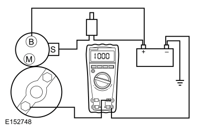
Starter Motor - Positive Circuit Test
NOTE: Always make the multimeter connection at the component terminal rather than at the wiring end of the connector. Making a connection at the wiring end of the connector could result in false readings because the meter will not pick up a high resistance between the wiring connector and component.
-
Make sure the battery is fully charged.
REFER to: Battery (414-01 Battery, Mounting and Cables, Diagnosis and Testing).
-
Perform a battery drain test.
REFER to: Battery Drain Check (414-01 Battery, Mounting and Cables, General Procedures).
-
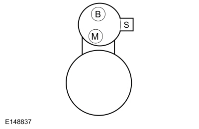
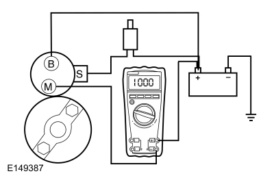
Connect a remote starter switch between starter solenoid “S” terminal and the battery positive terminal.
-
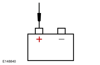
Connect the multimeter positive lead to the battery
positive post. Connect the negative lead to the starter solenoid "M"
terminal.
-
Place gear selector lever in Park or Neutral.
-
Engage the remote starter switch. Read and record the voltage. The voltage reading should be 0.5 volt or less.
-
If the voltage reading is 0.5 volt or less, perform Starter Motor - Ground Circuit Test in this section.
-
A voltage reading greater than 0.5 volt is an indication
of excessive resistance in the connections, the positive battery cable
or in the starter solenoid. Remove the cables from the solenoid "B", "S"
and "M" terminals. Clean the cables and connections and reinstall the
cables to the correct terminals. Repeat Steps 3 through 6.
-
If the voltage reading is still greater than 0.5 volt
when checked at the "M" terminal, move the multimeter negative lead to
the starter solenoid “B” terminal.
-
With the gear selector lever in Park or Neutral, engage the remote starter switch. Read and record the voltage.
-
If the voltage reading at the "B" terminal is lower than
0.5 volt, the concern is in the connections at the starter solenoid or
in the solenoid contacts. Install a new starter motor.
REFER to: Starter Motor (303-06A Starting System - 1.5L EcoBoost (118kW/160PS) – I4, Removal and Installation).
-
If the voltage reading taken at the solenoid "B"
terminal is greater than 0.5 volt after cleaning the cables and
connections at the solenoid, the concern is in the positive battery
cable connection or in the positive battery cable itself. Clean the
positive battery cable connection. If this does not resolve the concern,
install a new positive battery cable.
REFER to: Battery Cables - 1.5L EcoBoost (118kW/160PS) – I4 (414-01 Battery, Mounting and Cables, Removal and Installation).
Starter Motor - Ground Circuit Test
A slow cranking condition can be caused by resistance in the ground or return portion of the cranking circuit. This procedure checks the voltage drop in the ground circuit.
-
Connect a remote starter switch between starter solenoid "S" terminal and the battery positive terminal.
-
Connect the multimeter positive lead to the starter
motor housing (the connection must be clean and free of rust or grease).
Connect the negative lead to the negative battery terminal.
-
Place gear selector lever in Park or Neutral.
-
Engage the remote starter switch and crank the engine.
Read and record the voltage reading. The reading should be 0.5 volt or
less.
-
If the voltage reading is greater than 0.5 volt, clean
the negative cable connections at the battery, the body ground
connections and the starter ground connection. Retest.
-
If the voltage reading is greater than 0.5 volt, install a new negative battery cable.
REFER to: Battery Cables - 1.5L EcoBoost (118kW/160PS) – I4 (414-01 Battery, Mounting and Cables, Removal and Installation).
-
If the voltage reading is less than 0.5 volt and the engine still cranks slowly, install a new starter motor.
REFER to: Starter Motor (303-06A Starting System - 1.5L EcoBoost (118kW/160PS) – I4, Removal and Installation).
 Starting System - System Operation and Component Description. Description and Operation
System Operation
System Diagram
Network Message Chart
Module Network Input Messages Powertrain Control Module (PCM)
Broadcast Message
Originating Module
Message Purpose
Ignition status
BCM
Provides the PCM with ignition mode...
 Starter Motor Drive Gear and Flywheel Ring Gear Inspection. General Procedures
Inspection
Refer to: Starter Motor (303-06A Starting System - 1.5L EcoBoost (118kW/160PS) – I4, Removal and Installation).
Check the wear patterns on the starter drive gear and
the flywheel or flexplate ring gear...
Other information:
Ford Fusion 2013–2020 Service Manual: Rear Lamp Mounting Panel. Removal and Installation
Special Tool(s) / General Equipment Hot Air Gun 8 mm Drill Bit MIG/MAG Welding Equipment Spot Weld Drill Bit Materials Name Specification Seam SealerTA-2-B, 3M™ 08308, LORD Fusor® 803DTM - Removal WARNING: Before beginning any service procedure in this section, refer to Safety Warnings in section 100-00 General Information...
Ford Fusion 2013–2020 Service Manual: Accessory Drive Belt. Removal and Installation
Special Tool(s) / General Equipment Knife Removal NOTICE: Under no circumstances should the accessory drive belt, tensioner or pulleys be lubricated as potential damage to the belt material and tensioner damping mechanism will occur...
Categories
- Manuals Home
- 2nd Generation Ford Fusion Owners Manual
- 2nd Generation Ford Fusion Service Manual
- Under Hood Overview - 1.5L EcoBoost™, 2.0L EcoBoost™, 2.5L, 2.7L EcoBoost™
- Garage Door Opener
- Front Controls Interface Module (FCIM). Removal and Installation
- New on site
- Most important about car
Parallel Parking
The system detects available parallel parking spaces and steers your vehicle into the space. You control the accelerator, gearshift and brakes. The system visually and audibly guides you into a parallel parking space.
 Press the button once to search
for a parking space.
Press the button once to search
for a parking space.