Ford Fusion: Driving Aids
Ford Fusion 2013–2020 Owners Manual / Driving Aids
- Driver Alert
- Lane Keeping System (IF EQUIPPED)
- Blind Spot Information System (IF EQUIPPED)
- Cross Traffic Alert (IF EQUIPPED)
- Using Cross Traffic Alert
- Cross Traffic Alert System Sensors
- Cross Traffic Alert System Limitations
- Cross Traffic Alert Behavior When Trailer is Attached. Switching the System On and Off
- Cross Traffic Alert Indicator. Cross Traffic Alert Information Messages
- Steering
- Pre-Collision Assist (IF EQUIPPED)
 Hilly Condition Usage. Switching Adaptive Cruise Control
Off. Detection Issues
Hilly Condition Usage
Select a lower gear when the system is
active in situations such as prolonged
downhill driving on steep grades, for
example in mountainous areas...
 Driver Alert
Principle of Operation
WARNING: You are responsible for
controlling your vehicle at all times. The
system is designed to be an aid and does
not relieve you of your responsibility to
drive with due care and attention...
Other information:
Ford Fusion 2013–2020 Service Manual: Rear Side Member. Removal and Installation
Special Tool(s) / General Equipment Resistance Spotwelding Equipment 8 mm Drill Bit MIG/MAG Welding Equipment Spot Weld Drill Bit Locking Pliers Materials Name Specification Seam SealerTA-2-B, 3M™ 08308, LORD Fusor® 803DTM - Removal NOTICE: Battery electric vehicle (BEV), hybrid electric vehicle (HEV) and plug-in hybrid electric vehicle ..
Ford Fusion 2013–2020 Service Manual: Module Controlled Functions - System Operation and Component Description. Description and Operation
System Operation Battery Saver The battery saver feature is use to save battery voltage. The BCM provides automatic shut-off of the interior and exterior lamps after a time-out period when the ignition is off. For more information regarding the exterior lighting battery saver feature, Refer to: Exterior Lighting (417-01 Exterior Lighting) . For more information regarding the interior l..
Categories
- Manuals Home
- 2nd Generation Ford Fusion Owners Manual
- 2nd Generation Ford Fusion Service Manual
- Automatic Transmission - 6-Speed Automatic Transmission – 6F35
- Body Control Module (BCM). Removal and Installation
- Traction Control
- New on site
- Most important about car
Direction Indicators. Interior Lamps
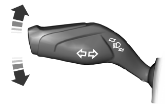
Direction Indicators

Push the lever up or down to use the direction indicators.
Copyright © 2026 www.fofusion2.com
