Ford Fusion: Interior Lighting / Interior Lighting - System Operation and Component Description. Description and Operation
System Operation
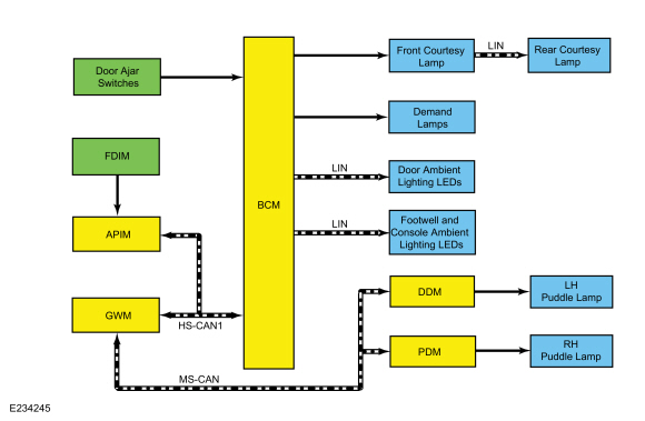
System Diagram
.jpg)
| Item | Description |
|---|---|
| 1 | LIN |
| 2 | LIN |
| 3 | LIN |
| 4 | BCM |
| 5 | Front courtesy lamp |
| 6 | Rear courtesy lamp |
| 7 | MS-CAN |
| 8 | DDM |
| 9 | LH puddle lamp |
| 10 | RH puddle lamp |
| 11 | Door ambient lighting Light Emitting Diodes (LEDs) |
| 12 | Demand lamps |
| 13 | PDM |
| 14 | Door ajar switches |
| 15 | Footwell and console ambient lighting Light Emitting Diodes (LEDs) |
| 16 | APIM |
| 17 | FDIM |
| 18 | GWM |
| 19 | HS-CAN1 |
Network Message Chart
DDM And PDM Network Input Messages
| Broadcast Message | Originating Module | Message Purpose |
|---|---|---|
| Puddle lamp activation | BCM | Provides puddle lamp request from the BCM to activate the exterior mirror puddle lamps. |
GWM Network Input Messages
| Broadcast Message | Originating Module | Message Purpose |
|---|---|---|
| Ambient light color/intensity request | APIM | Indicates the color and brightness setting selected from the display interface. This commands the ambient color and brightness setting as requested by the operator. |
BCM Network Input Messages
| Broadcast Message | Originating Module | Message Purpose |
|---|---|---|
| Ambient light color/intensity request | GWM | Indicates the color and brightness setting selected from the display interface. This commands the ambient color and brightness setting as requested by the operator. |
Battery Saver
NOTE: Time-out is 10 seconds if the vehicle is in factory mode or 0 seconds if the vehicle is in transport mode.
The BCM automatically shuts off of the courtesy and demand lamps after a time-out period when the ignition is OFF. A timer in the BCM starts when:
- the ignition transitions to OFF.
- any door or liftgate/luggage compartment lid becomes ajar.
- the UNLOCK button of an RKE transmitter is pressed.
- a door is unlocked using a key.
- the door lock switch is pressed.
When 10 minutes (30 minutes for demand lamps) have elapsed, the BCM automatically shuts off voltage to the lamps. The timer restarts (voltage is restored if the BCM is in battery saver mode) if:
- the ignition transitions out of OFF.
- any door or liftgate/luggage compartment lid becomes ajar.
- the UNLOCK button of the RKE transmitter is pressed.
- a door is unlocked using a key.
- the door lock switch is pressed.
Courtesy Lamps
The BCM controls the courtesy lighting functions and timing by monitoring inputs from the following:
- Door ajar switches
- Ignition state
- RKE system
The DDM and PDM provide voltage to the left and right puddle lamps based on messaged input from the BCM over the communication network.
The BCM sends a voltage signal to each door ajar switch. When the doors are closed, the circuit is switched to ground and the voltage is pulled low, indicating closed doors.
The DDM and PDM provide ground for the door ajar switch.
The BCM monitors the ignition state and inputs from the RKE system to determine when to energize the interior light relay. When the interior light relay is energized, voltage is provided to the interior lamps. The BCM controls the ground side of the courtesy lamps for the illuminated entry and exit features.
For keyless entry, the BCM monitors input from the RKE transmitter or the RFA module to determine when to activate/deactivate the illuminated entry and exit functions.
The interior courtesy lamps are also activated from the courtesy lamp switch mounted on the front interior lamp. The front interior lamp controls the courtesy lamp function of the rear interior lamp. When the courtesy lamp button is pressed on the front interior lamp, the courtesy lamp function for all the lamps is turned on/off. If any door is open, the BCM command overrides the function of the front courtesy lamp switch and activates the courtesy lamps.
Illuminated Entry and Exit
The illuminated entry and exit features provide temporary illumination of the parking lamps, the dimmable backlighting, the ambient backlighting and the courtesy lamps. Refer to the table for additional information.
NOTE: An arbitrator (software programming) within the BCM determines which actions take precedence over others (for example, an open door keeps the courtesy lamps on even when a command to lock the doors is received).
| Action | Parking Lamps | Courtesy Lamps | Dimmable Backlighting | Ambient Lighting |
|---|---|---|---|---|
| RKE transmitter or mechanical unlocking of the doors | On for 25 seconds | On for 25 seconds | On for 25 seconds | Off |
| RKE transmitter or mechanical locking of the doors | Off | Off | Off | Off 3 seconds after courtesy lamps turn off |
| Open a closed door after previously unlocking (no ignition state change since unlock) | Off (on for remaining time if unlocked from transmitter or mechanical unlocking of the doors) | On | On | On |
| Close all doors | Off | On for 25 seconds | On for 25 seconds | On for 25 seconds |
| Ignition changed to ON | Off | On for 25 seconds | Off | On |
| Ignition changed out of ON | Off | On for 25 seconds | On for 25 seconds | On for 25 seconds |
| Open a door after the ignition is changed to OFF | Off | On | Off | On (color is red on the open door) |
| Ignition is OFF and doors are unlocked from the door lock switch | Off | On for 25 seconds | Off | Off |
| Ignition is OFF and doors are locked from the door lock switch | Off | Off | Off | Off |
Demand Lamps
When the BCM is in not in battery saver mode, the interior light relay is energized to provide voltage to the demand lamps.
The BCM supplies voltage signal to the luggage compartment lamp. The luggage compartment lid ajar switch is grounded. When the luggage compartment lid is opened, the luggage compartment lamp is grounded.
Ambient Lighting
The ambient lighting subsystem consists of the BCM, and the Light Emitting Diodes (LEDs) located within the floor console, door panels and under the instrument panel footwell areas. The ambient lighting is operational when the ignition is in any state other than OFF (the exception is when it is used in conjunction with the illuminated entry/exit features), the headlamps are on and the outside ambient light level is low. The BCM provides the voltage to the ambient lighting system, while the FDIM (touchscreen) is used to cycle through the different color variations or turn the ambient lighting feature on or off. A LIN circuit is routed from the BCM to all of the Light Emitting Diodes (LEDs). There are 3 Light Emitting Diodes (LEDs) (red, blue and green) housed within each LED assembly. By illuminating various color combinations, the Light Emitting Diodes (LEDs) are able to produce 7 different colors of ambient light.
The APIM uses software to monitor the user interface from the FDIM. Based on the ambient lighting system selections made using the FDIM, the APIM sends ambient light color request and ambient light intensity request messages over the communication network for color and brightness settings. The BCM retains the last color and brightness setting between uses.
Field Effect Transistor (FET) Protection
A Field Effect Transistor (FET) is a type of transistor that, when used with module software, monitors and controls current flow on module outputs. The Field Effect Transistor (FET) protection strategy prevents module damage in the event of excessive current flow.
The BCM utilizes a Field Effect Transistor (FET) protective circuit strategy for many of its outputs (for example, a headlamp output circuit). Output loads (current level) are monitored for excessive current (typically short circuits) and are shut down (turns off the voltage or ground provided by the module) when a fault event is detected. A short circuit DTC is stored at the fault event and a cumulative counter is started.
When the demand for the output is no longer present, the module resets the Field Effect Transistor (FET) circuit protection to allow the circuit to function. The next time the driver requests a circuit to activate that has been shut down by a previous short (Field Effect Transistor (FET) protection) and the circuit is still shorted, the Field Effect Transistor (FET) protection shuts off the circuit again and the cumulative counter advances.
When the excessive circuit load occurs often enough, the module shuts down the output until a repair procedure is carried out. Each Field Effect Transistor (FET) protected circuit has 3 predefined levels of short circuit tolerance based on the harmful effect of each circuit fault on the Field Effect Transistor (FET) and the ability of the Field Effect Transistor (FET) to withstand it. A module lifetime level of fault events is established based upon the durability of the Field Effect Transistor (FET). If the total tolerance level is determined to be 600 fault events, the 3 predefined levels would be 200, 400 and 600 fault events.
When each tolerance level is reached, DTC U1000:00 sets along with the short circuit DTC that was stored on the first failure. These Diagnostic Trouble Codes (DTCs) cannot be cleared until the vehicle is repaired.
After the repair, it is necessary to clear the Diagnostic Trouble Codes (DTCs). Use the clear DTC operation on the scan tool, cycle the ignition, and run the BCM on-demand self-test.
The module never resets the fault event counter to zero and continues to advance the fault event counter as short circuit fault events occur. If the number of short circuit fault events reach the third level, DTC U3000:49 sets along with the associated short circuit DTC. DTC U3000:49 cannot be cleared and the module must be replaced after the initial fault is repaired.
Component Description
Door Ajar Switch
The door ajar switches (ground switches) each receive a voltage signal from the BCM on independent circuits. When the door is closed, the door ajar switch is closed, routing the signal to ground. When the door is opened, the door ajar switch opens.
Ground is provided to the door ajar switches from the door modules.
Luggage Compartment Lid Ajar Switch
The luggage compartment lid ajar switch (ground switch) receives a voltage signal from the BCM. When the luggage compartment lid is closed, the luggage compartment lid ajar switch is closed, routing the signal to ground. When the luggage compartment lid is opened, the door ajar switch opens.
Interior Lamp
All of the interior lamps receive voltage from the interior lamp relay (integrated into the BCM) when the battery saver feature is not active. This is used by each interior lamp to power the LED within it.
The front interior lamp sends a message to the rear lamp to activate/deactivate it through a LIN circuit.
A dedicated ground circuit is provided for map lamp functionality.

 Interior Lighting. Diagnosis and Testing
DTC Chart: BCM
Diagnostics in this manual assume a certain skill level and knowledge of Ford-specific diagnostic practices. REFER to: Diagnostic Methods (100-00 General Information, Description and Operation)...
Other information:
Ford Fusion 2013–2020 Service Manual: Evaporative Emission Canister Purge Valve. Removal and Installation
Removal NOTE: Removal steps in this procedure may contain installation details. Remove the engine appearance cover. Remove the air cleaner outlet pipe. Refer to: Air Cleaner Outlet Pipe (303-12A Intake Air Distribution and Filtering - 1...
Ford Fusion 2013–2020 Service Manual: Parking Brake. Diagnosis and Testing
DTC Chart: Anti-Lock Brake System (ABS) Module Diagnostics in this manual assume a certain skill level and knowledge of Ford-specific diagnostic practices. REFER to: Diagnostic Methods (100-00 General Information, Description and Operation). NOTE: If present, diagnose DTC C2007:13 Right Motor: Circuit Open or C2008:13 Left Motor: Circuit Open before diagnosing all other Diagnostic Trou..
Categories
- Manuals Home
- 2nd Generation Ford Fusion Owners Manual
- 2nd Generation Ford Fusion Service Manual
- Automatic Transmission Fluid Check - 1.5L EcoBoost™/2.0L EcoBoost™/2.5L. Automatic Transmission Fluid Check - 2.7L EcoBoost™
- Main Control Valve Body. Removal and Installation
- Under Hood Overview - 1.5L EcoBoost™, 2.0L EcoBoost™, 2.5L, 2.7L EcoBoost™
- New on site
- Most important about car
Parallel Parking
The system detects available parallel parking spaces and steers your vehicle into the space. You control the accelerator, gearshift and brakes. The system visually and audibly guides you into a parallel parking space.
 Press the button once to search
for a parking space.
Press the button once to search
for a parking space.