Ford Fusion: Roof Opening Panel / Roof Opening Panel Alignment. General Procedures
Ford Fusion 2013–2020 Service Manual / Body and Paint / Body and Paint / Roof Opening Panel / Roof Opening Panel Alignment. General Procedures
Adjustment
 WARNING:
Before beginning any service procedure in this section,
refer to Safety Warnings in section 100-00 General Information. Failure
to follow this instruction may result in serious personal injury.
-
Refer to: Health and Safety Precautions (100-00 General Information, Description and Operation).
-
On both sides.
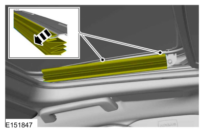
Detach the top portion of the roof opening panel blind and fold it down to get access to the roof opening panel glass retainers.
 |
-
NOTE: Roof opening panel blind removed for clarity.
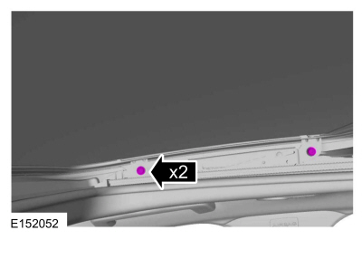
On both sides.
Loosen the retainers for adjustment.
 |
-
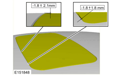
Measure and if necessary, adjust the front sliding glass panel to roof and roof height at the front of the glass as shown.
-
Center line -1.8 +/- 2.1mm
-
Outboard line -1.8 +/- 1.8mm
-
Center line -1.8 +/- 2.1mm
 |
-
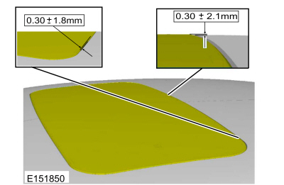
Measure and if necessary, adjust the front sliding glass panel to roof and roof height at the rear of the glass as shown.
-
Outboard line 0.30 +/- 1.8mm
-
Center line 0.30 +/- 2.1mm
-
Outboard line 0.30 +/- 1.8mm
 |
-
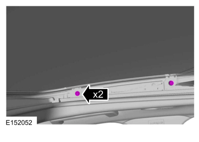
On Both sides.
Tighten the retainers.
Torque: 53 lb.in (6 Nm)
 |
-
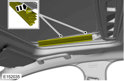
On Both sides.
Attach the top portion of the roof opening panel blind to the drip link.
 |
-
Initialize the power roof opening panel.
Refer to: Power Roof Opening Panel Initialization (501-17 Roof Opening Panel, General Procedures).
 Power Roof Opening Panel Initialization. General Procedures
Initialization
WARNING:
Keep objects and body parts clear of the glass panel when
carrying out the initialization procedure. During the initialization
procedure, the glass panel closes with high force and cannot detect
objects in its path...
 Timing Adjustment. General Procedures
Special Tool(s) /
General Equipment
Flat-Bladed Screwdriver
Adjustment
NOTICE:
A new frame assembly is not equipped with a motor. When a
motor is not installed, and the frame is moved, the cables/mechanisms
can experience free-play movement causing the timing to become out of
adjustment...
Other information:
Ford Fusion 2013–2020 Service Manual: Climate Control System - Vehicles With: Electronic Manual Temperature Control (EMTC) - Overview. Description and Operation
Overview The Electronic Manual Temperature Control (EMTC) system heats or cools the vehicle depending on the HVAC control panel selection. The control panel selection determines heating or cooling, air distribution and enables blower motor operation...
Ford Fusion 2013–2020 Service Manual: Front Door Window Glass. Removal and Installation
Removal NOTE: LH side shown, RH side similar. Remove the front door trim panel. Refer to: Front Door Trim Panel (501-05 Interior Trim and Ornamentation, Removal and Installation). Remove the front door speaker. Refer to: Front Door Speaker (415-00 Information and Entertainment System - General Information - Vehicles With: AM/FM/CD/SYNC/Sony Audio System) ...
Categories
- Manuals Home
- 2nd Generation Ford Fusion Owners Manual
- 2nd Generation Ford Fusion Service Manual
- Memory Function
- Intake Manifold. Removal and Installation
- Pre-Collision Assist (IF EQUIPPED)
- New on site
- Most important about car
Direction Indicators. Interior Lamps
Direction Indicators
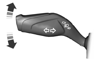
Push the lever up or down to use the direction indicators.
Copyright © 2026 www.fofusion2.com
