Ford Fusion: Steering Wheel and Column Electrical Components / Ignition Lock Cylinder Housing. Removal and Installation
Ford Fusion 2013–2020 Service Manual / Chassis / Steering System / Steering Wheel and Column Electrical Components / Ignition Lock Cylinder Housing. Removal and Installation
Removal
-
Follow the health and safety precautions. WARNING:
Before beginning any service procedure in this
section, refer to Safety Warnings in section 100-00 General Information.
Failure to follow this instruction may result in serious personal
injury.
WARNING:
Before beginning any service procedure in this
section, refer to Safety Warnings in section 100-00 General Information.
Failure to follow this instruction may result in serious personal
injury.
Refer to: Health and Safety Precautions (100-00 General Information, Description and Operation).
-
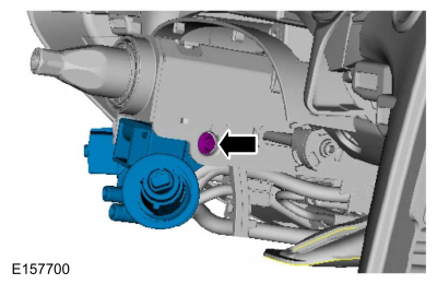
Remove the SCCM.
Refer to: Steering Column Control Module (SCCM) (211-05 Steering Wheel and Column Electrical Components, Removal and Installation).
-
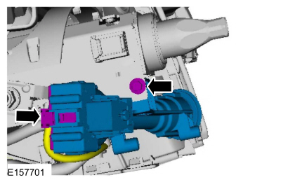
Remove the RH side bolt.
 |
-
Disconnect the electrical connector and remove the LH side bolt.
 |
Installation
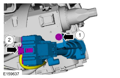
NOTICE: The ignition lock cylinder housing bolts must be tightened in the order of the following steps. Otherwise, binding of the ignition cylinder and ignition switch may occur.
-
Install the RH side bolt.
 |
-
Install the LH side bolt and connect the electrical connector.
 |
-
Install the SCCM.
Refer to: Steering Column Control Module (SCCM) (211-05 Steering Wheel and Column Electrical Components, Removal and Installation).
 Steering Wheel Multifunction Switch. Removal and Installation
Special Tool(s) /
General Equipment
Interior Trim Remover
Removal
NOTE:
Removal steps in this procedure may contain installation details...
 Heated Steering Wheel Module (HSWM). Removal and Installation
Removal
NOTE:
Removal steps in this procedure may contain installation details.
NOTE:
This step is only necessary when installing a new component...
Other information:
Ford Fusion 2013–2020 Service Manual: Universal Serial Bus (USB) Hub. Removal and Installation
Special Tool(s) / General Equipment Interior Trim Remover Removal Remove the USB port bezel. Disconnect the electrical connectors. Use the General Equipment: Interior Trim Remover Installation To install, reverse the removal procedure...
Ford Fusion 2013–2020 Service Manual: Direct Current/Alternating Current (DC/AC) Inverter - System Operation and Component Description. Description and Operation
System Diagram System Operation Network Message Chart Broadcast Message Originating Module Message Purpose Power pack torque status Secondary On-Board Diagnostic Control Module C (SOBDMC) Used to determine if the vehicle is started or if torque is available...
Categories
- Manuals Home
- 2nd Generation Ford Fusion Owners Manual
- 2nd Generation Ford Fusion Service Manual
- Engine - 1.5L EcoBoost (118kW/160PS) – I4
- Transmission - 1.5L EcoBoost (118kW/160PS) – I4. Removal and Installation
- Under Hood Overview - 1.5L EcoBoost™, 2.0L EcoBoost™, 2.5L, 2.7L EcoBoost™
- New on site
- Most important about car
Cross Traffic Alert System Sensors
The sensors are behind the rear bumper on both sides of your vehicle.
Copyright © 2026 www.fofusion2.com