Ford Fusion: Rear Disc Brake / Brake Disc. Removal and Installation
Materials
| Name | Specification |
|---|---|
| Motorcraft® Metal Brake Parts Cleaner PM-4-A, PM-4-B |
- |
Removal
NOTE: Removal steps in this procedure may contain installation instructions.
-
Activate the EPB service mode. WARNING:
Service actions on vehicles equipped with electronic
parking brakes may cause unexpected parking brake application, which
could result in injury to hands or fingers. Deactivate the electronic
parking brake system prior to servicing or removing rear brake
components. Failure to follow this instruction may result in serious
personal injury.
WARNING:
Service actions on vehicles equipped with electronic
parking brakes may cause unexpected parking brake application, which
could result in injury to hands or fingers. Deactivate the electronic
parking brake system prior to servicing or removing rear brake
components. Failure to follow this instruction may result in serious
personal injury.
Refer to: Electronic Parking Brake (EPB) Service Mode Activation and Deactivation (206-05 Parking Brake and Actuation, General Procedures).
-
Remove the wheel and tire.
Refer to: Wheel and Tire (204-04A Wheels and Tires, Removal and Installation).
-
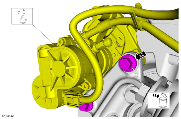
Remove the bolts and position the brake caliper and anchor plate assembly aside. Discard the bolts.
Torque: 76 lb.ft (103 Nm)
 |
-
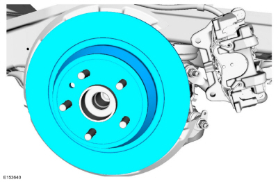
Remove the brake disc.
 |
-
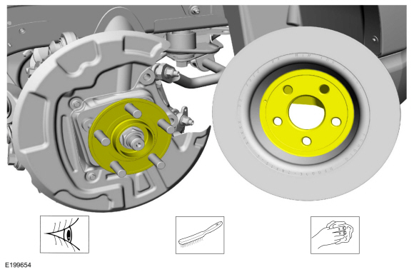
NOTICE: Make sure that the mating faces are clean and free of foreign material.
Clean the brake disc-to-wheel hub mating surfaces.
Material: Motorcraft® Metal Brake Parts Cleaner / PM-4-A, PM-4-B
 |
Installation
-
NOTICE: Make sure that the brake hose is not twisted when installing the brake caliper or damage to the brake flexible hose may occur.
To install, reverse the removal procedure.
-
Deactivate the EPB service mode.
Refer to: Electronic Parking Brake (EPB) Service Mode Activation and Deactivation (206-05 Parking Brake and Actuation, General Procedures).
-
Apply the brake pedal several times to verify correct brake system operation.
 Brake Caliper Anchor Plate. Removal and Installation
Removal
NOTE:
Steps in the removal procedure may contain installation details.
Remove the brake pads.
Refer to: Brake Pads (206-04 Rear Disc Brake, Removal and Installation)...
 Brake Disc Shield. Removal and Installation
Removal
NOTE:
Removal steps in this procedure may contain installation details.
Remove the brake disc.
Refer to: Brake Disc (206-04 Rear Disc Brake, Removal and Installation)...
Other information:
Ford Fusion 2013–2020 Owners Manual: Safety Canopy™
WARNING: Do not place objects or mount equipment on or near the headliner at the siderail that may come into contact with a deploying curtain airbag. Failure to follow these instructions may increase the risk of personal injury in the event of a crash...
Ford Fusion 2013–2020 Service Manual: Parking Brake - Overview. Description and Operation
Overview The parking brake system uses 2 switch activated, Electronic Control Unit (ECU) controlled motors to apply and release the rear brake calipers. The ABS module controls and monitors the parking brake system and sets Diagnostic Trouble Codes (DTCs) when a fault is present in the system...
Categories
- Manuals Home
- 2nd Generation Ford Fusion Owners Manual
- 2nd Generation Ford Fusion Service Manual
- Intake Manifold. Removal and Installation
- Powertrain
- Body Control Module (BCM). Removal and Installation
- New on site
- Most important about car
Cross Traffic Alert System Sensors
The sensors are behind the rear bumper on both sides of your vehicle.