Ford Fusion: Rear End Sheet Metal Repairs / Front Floor Panel Upper Rear Crossmember. Removal and Installation
Special Tool(s) / General Equipment
| 8 mm Drill Bit | |
| MIG/MAG Welding Equipment | |
| Spot Weld Drill Bit | |
| Locking Pliers |
Materials
| Name | Specification |
|---|---|
| Seam Sealer TA-2-B, 3M™ 08308, LORD Fusor® 803DTM |
- |
Removal
NOTICE: Battery electric vehicle (BEV), hybrid electric vehicle (HEV) and plug-in hybrid electric vehicle (PHEV) contain a high-voltage battery. Before cutting or welding near the high-voltage battery it must be removed to avoid damage.
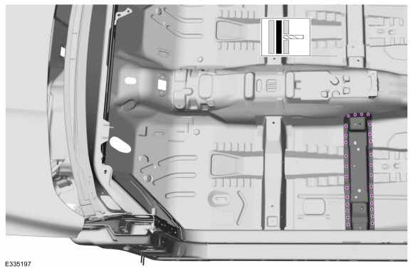
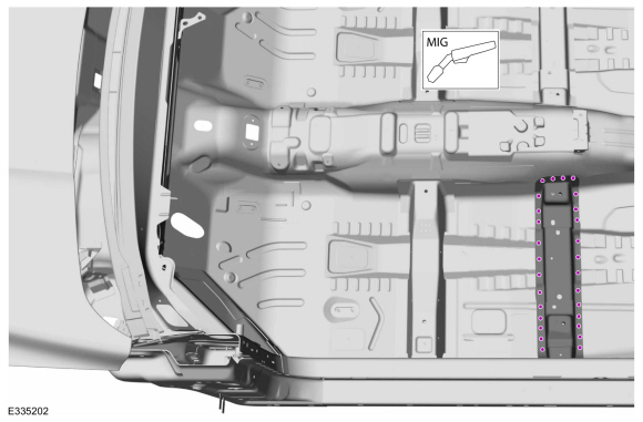
NOTE: Left hand (LH) side shown, right hand (RH) side similar.
NOTE: Roof and body side removed for clarity.
NOTE: Factory welds may be substituted with resistance or metal inert gas (MIG) plug welds. Resistance welds may not be placed directly over original location. They must be placed adjacent to original location and match factory welds in quantity. Metal inert gas (MIG) plug welds must equal factory welds in both location and quantity.
NOTE: Adequately protect all adjacent areas against cutting, grinding and welding procedures.
-
Depower the SRS.
Refer to: Supplemental Restraint System (SRS) Depowering and Repowering (501-20B) .
-
If Required:
Dimensionally restore the vehicle to pre-damage condition.
Refer to: Body and Frame (501-26) .
-
Remove the front seat.
Refer to: Front Seat Track (501-10A Front Seats, Removal and Installation).
-
If Equipped:
Remove the center console.
Refer to: Floor Console (501-12) .
-
Remove the A and B-pillar trim panels.
Refer to: A-Pillar Trim Panel (501-05) .
Refer to: B-Pillar Trim Panel (501-05) .
-
Position the carpet and all wiring harnesses away from the working area.
-
Remove the welds.
Use the General Equipment: Spot Weld Drill Bit
 |
-
Remove the welds.
Use the General Equipment: Spot Weld Drill Bit
 |
-
NOTE: Pay particular attention the location of adhesives, sealers and NVH materials to aid in installation.
Remove the crossmember.
 |
Installation
NOTICE: Battery electric vehicle (BEV), hybrid electric vehicle (HEV) and plug-in hybrid electric vehicle (PHEV) contain a high-voltage battery. Before cutting or welding near the high-voltage battery it must be removed to avoid damage.
NOTICE: The high-voltage battery in a battery electric vehicle (BEV), hybrid electric vehicle (HEV) or plug-in hybrid electric vehicle (PHEV) can be affected and damaged by excessively high temperatures. The temperature in some body shop paint booths can exceed 60° C (140° F). Therefore, during refinishing operations, the paint booth temperature must set at or below 60° C (140° F) with a bake time of 45 minutes or less. Temperatures in excess of 60° C (140° F) or bake durations longer than 45 minutes will require the high-voltage battery be removed from the vehicle prior to placing in the paint booth.
NOTICE: If refinishing cure temperatures exceed 60° C (140° F), the charge port light ring on plug-in vehicles must be removed.
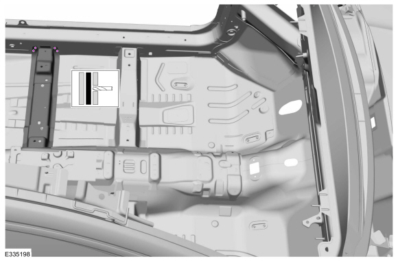
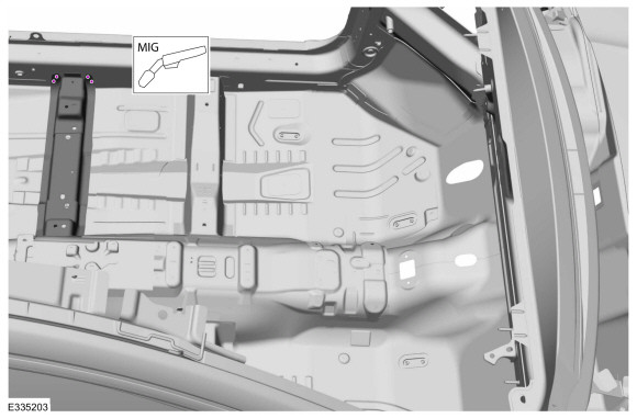
NOTE: Left hand (LH) side shown, right hand (RH) side similar.
NOTE: Roof and body side removed for clarity.
NOTE: Factory welds may be substituted with resistance or metal inert gas (MIG) plug welds. Resistance welds may not be placed directly over original location. They must be placed adjacent to original location and match factory welds in quantity. Metal inert gas (MIG) plug welds must equal factory welds in both location and quantity.
NOTE: Adequately protect all adjacent areas against cutting, grinding and welding procedures.
-
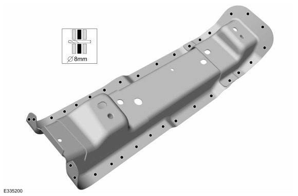
Drill plug weld holes in the replacement rear crossmember.
Use the General Equipment: 8 mm Drill Bit
 |
-
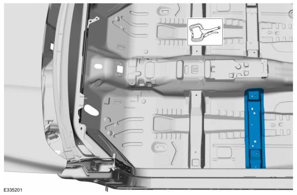
Install, properly position and clamp the rear crossmember.
Use the General Equipment: Locking Pliers
 |
-
Install the welds.
Use the General Equipment: MIG/MAG Welding Equipment
 |
-
Install the welds.
Use the General Equipment: MIG/MAG Welding Equipment
 |
-
Dress all welds as required using typical metal finishing techniques.
-
Seam Sealing:
All seams must be sealed to production level.
Material: Seam Sealer / TA-2-B, 3M™ 08308, LORD Fusor® 803DTM
-
Refinish the entire repair using a Ford approved paint system.
-
Reposition all wiring harnesses and the carpet to original locations.
-
If Equipped:
Install the center console.
Refer to: Floor Console (501-12) .
-
Install the front seat.
Refer to: Front Seat Track (501-10A Front Seats, Removal and Installation).
Refer to: Front Seat (501-10A Front Seats, Removal and Installation).
-
Install the A and B-pillar trim panels.
Refer to: B-Pillar Trim Panel (501-05) .
Refer to: A-Pillar Trim Panel (501-05) .
-
Restore corrosion protection.
Refer to: Corrosion Prevention (501-25 Body Repairs - General Information, General Procedures).
-
Repower the SRS.
Refer to: Supplemental Restraint System (SRS) Depowering and Repowering (501-20B) .

 Inner Quarter Panel and Wheelhouse. Removal and Installation
Special Tool(s) /
General Equipment
Resistance Spotwelding Equipment
Spherical Cutter
Air Body Saw
8 mm Drill Bit
MIG/MAG Welding Equipment
Spot Weld Drill Bit
Locking Pliers
Materials
Name
Specification
Seam SealerTA-2-B, 3M™ 08308, LORD Fusor® 803DTM
-
Flexible Foam Repair3M™ 08463, LORD Fusor® 121
-
Removal
..
Other information:
Ford Fusion 2013–2020 Service Manual: Connecting Rod Bearing Journal Clearance. General Procedures
Check NOTE: Refer to the appropriate Section 303-01 for the specification. NOTE: The crankshaft connecting rod journals must be within specifications to check the connecting rod bearing journal clearance. Remove the connecting rod bearing cap and connecting rod bearing. Position a piece of Plastigage across the bearing surface. NOTE: D..
Ford Fusion 2013–2020 Service Manual: Glass, Frames and Mechanisms - System Operation and Component Description. Description and Operation
System Operation System Diagram - Power Windows Driver Side Windows Passenger Side Windows Network Message Chart - Power Windows Passenger Door Module (PDM) Network Input Messages Broadcast Message Originating Module Message Purpose Passenger window command DDM When activating the front ..
Categories
- Manuals Home
- 2nd Generation Ford Fusion Owners Manual
- 2nd Generation Ford Fusion Service Manual
- Electrical
- Memory Function
- Powertrain
- New on site
- Most important about car
Fuel Quality
Choosing the Right Fuel
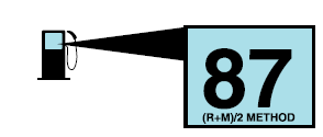
Your vehicle is designed to operate on regular unleaded gasoline with a minimum pump (R+M)/2 octane rating of 87.