Ford Fusion: Rear End Sheet Metal Repairs / Front Floor Panel Upper Front Crossmember. Removal and Installation
Special Tool(s) / General Equipment
| 8 mm Drill Bit | |
| MIG/MAG Welding Equipment | |
| Spot Weld Drill Bit | |
| Locking Pliers |
Materials
| Name | Specification |
|---|---|
| Seam Sealer TA-2-B, 3M™ 08308, LORD Fusor® 803DTM |
- |
Removal
NOTICE: Battery electric vehicle (BEV), hybrid electric vehicle (HEV) and plug-in hybrid electric vehicle (PHEV) contain a high-voltage battery. Before cutting or welding near the high-voltage battery it must be removed to avoid damage.
NOTE: Left hand (LH) side shown, right hand (RH) side similar.
NOTE: Roof and body side removed for clarity.
NOTE: Factory welds may be substituted with resistance or metal inert gas (MIG) plug welds. Resistance welds may not be placed directly over original location. They must be placed adjacent to original location and match factory welds in quantity. Metal inert gas (MIG) plug welds must equal factory welds in both location and quantity.
NOTE: Adequately protect all adjacent areas against cutting, grinding and welding procedures.
-
Depower the SRS.
Refer to: Supplemental Restraint System (SRS) Depowering and Repowering (501-20B) .
-
If Required:
Dimensionally restore the vehicle to pre-damage condition.
Refer to: Body and Frame (501-26) .
-
Remove the front seat.
Refer to: Front Seat Track (501-10A Front Seats, Removal and Installation).
-
If Equipped:
Remove the center console.
Refer to: Floor Console (501-12) .
-
Remove the A and B-pillar trim panels.
Refer to: A-Pillar Trim Panel (501-05) .
Refer to: B-Pillar Trim Panel (501-05) .
-
Position the carpet and all wiring harnesses away from the working area.
-
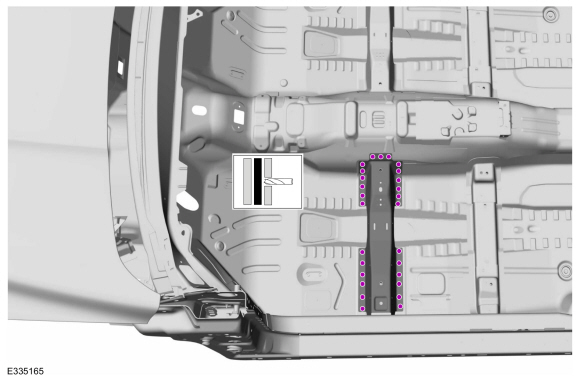
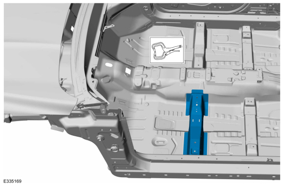
Remove the welds.
Use the General Equipment: Spot Weld Drill Bit
 |
-
Remove the welds.
Use the General Equipment: Spot Weld Drill Bit
 |
-
NOTE: Pay particular attention the location of adhesives, sealers and NVH materials to aid in installation.
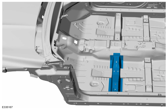
Remove the forward crossmember.
 |
Installation
NOTICE: Battery electric vehicle (BEV), hybrid electric vehicle (HEV) and plug-in hybrid electric vehicle (PHEV) contain a high-voltage battery. Before cutting or welding near the high-voltage battery it must be removed to avoid damage.
NOTICE: The high-voltage battery in a battery electric vehicle (BEV), hybrid electric vehicle (HEV) or plug-in hybrid electric vehicle (PHEV) can be affected and damaged by excessively high temperatures. The temperature in some body shop paint booths can exceed 60° C (140° F). Therefore, during refinishing operations, the paint booth temperature must set at or below 60° C (140° F) with a bake time of 45 minutes or less. Temperatures in excess of 60° C (140° F) or bake durations longer than 45 minutes will require the high-voltage battery be removed from the vehicle prior to placing in the paint booth.
NOTICE: If refinishing cure temperatures exceed 60° C (140° F), the charge port light ring on plug-in vehicles must be removed.
NOTE: Left hand (LH) side shown, right hand (RH) side similar.
NOTE: Roof and body side removed for clarity.
NOTE: Factory welds may be substituted with resistance or metal inert gas (MIG) plug welds. Resistance welds may not be placed directly over original location. They must be placed adjacent to original location and match factory welds in quantity. Metal inert gas (MIG) plug welds must equal factory welds in both location and quantity.
NOTE: Adequately protect all adjacent areas against cutting, grinding and welding procedures.
-
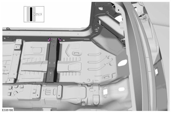
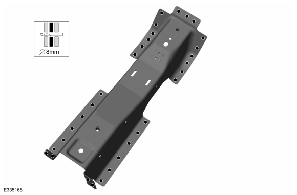
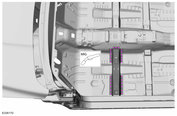
Drill plug weld holes in the replacement forward crossmember.
Use the General Equipment: 8 mm Drill Bit
 |
-
Install, properly position and clamp the forward crossmember.
Use the General Equipment: Locking Pliers
 |
-
Install the welds.
Use the General Equipment: MIG/MAG Welding Equipment
 |
-
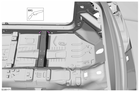
Install the welds.
Use the General Equipment: MIG/MAG Welding Equipment
 |
-
Dress all welds as required using typical metal finishing techniques.
-
Seam Sealing:
All seams must be sealed to production level.
Material: Seam Sealer / TA-2-B, 3M™ 08308, LORD Fusor® 803DTM
-
Refinish the entire repair using a Ford approved paint system.
-
Reposition all wiring harnesses and the carpet to original locations.
-
If Equipped:
Install the center console.
Refer to: Floor Console (501-12) .
-
Install the front seat.
Refer to: Front Seat Track (501-10A Front Seats, Removal and Installation).
Refer to: Front Seat (501-10A Front Seats, Removal and Installation).
-
Install the A and B-pillar trim panels.
Refer to: B-Pillar Trim Panel (501-05) .
Refer to: A-Pillar Trim Panel (501-05) .
-
Restore corrosion protection.
Refer to: Corrosion Prevention (501-25 Body Repairs - General Information, General Procedures).
-
Repower the SRS.
Refer to: Supplemental Restraint System (SRS) Depowering and Repowering (501-20B) .

 Front Floor Panel Upper Rear Crossmember. Removal and Installation
Special Tool(s) /
General Equipment
8 mm Drill Bit
MIG/MAG Welding Equipment
Spot Weld Drill Bit
Locking Pliers
Materials
Name
Specification
Seam SealerTA-2-B, 3M™ 08308, LORD Fusor® 803DTM
-
Removal
NOTICE:
Battery electric vehicle (BEV), hybrid electric vehicle
(HEV) and plug-in hybrid electric vehicle (PHEV) contain a high-voltage
battery..
Other information:
Ford Fusion 2013–2020 Service Manual: Fuel Filler Door. Removal and Installation
Removal Open the fuel filler door. Using a screwdriver, pry the retaining tab back and slide the fuel filler door from the fuel filler door hinge. Installation To install, reverse the removal procedure. ..
Ford Fusion 2013–2020 Service Manual: Seat Heater Mat Removal. General Procedures
Repair WARNING: To minimize the risk of injury, always wear protective gloves when working with a steamer. Failure to follow these instructions may result in serious personal injury. NOTE: Click here to view a video version of the seat heater mat removal and installation. View NOTE: During installation, it is allowable to adhere a new heater mat to any adhesiv..
Categories
- Manuals Home
- 2nd Generation Ford Fusion Owners Manual
- 2nd Generation Ford Fusion Service Manual
- Cylinder Head. Removal and Installation
- Starter Motor. Removal and Installation
- Traction Control
- New on site
- Most important about car
Using Seatbelts During Pregnancy
WARNING: Always ride and drive with your seatback upright and properly fasten your seatbelt. Fit the lap portion of the seatbelt snugly and low across the hips. Position the shoulder portion of the seatbelt across your chest. Pregnant women must follow this practice. See the following figure.
