Ford Fusion: Glass, Frames and Mechanisms / Glass, Frames and Mechanisms - System Operation and Component Description. Description and Operation
System Operation
System Diagram - Power Windows
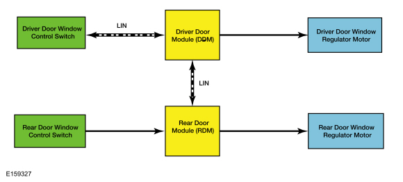
Driver Side Windows
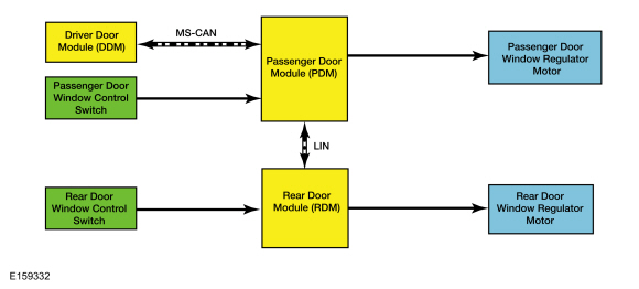
Passenger Side Windows
Network Message Chart - Power Windows
Passenger Door Module (PDM) Network Input Messages
| Broadcast Message | Originating Module | Message Purpose |
|---|---|---|
| Passenger window command | DDM | When activating the front or rear passenger windows from the driver door window control switch, the passenger window command is sent from the DDM to the PDM. |
| Rear window disable command | DDM | When the lock-out switch (located in the driver door window control switch) is in the LOCK position, the DDM sends this command to the PDM to disable the passenger rear door window regulator motor from operating from the rear door window control switch. |
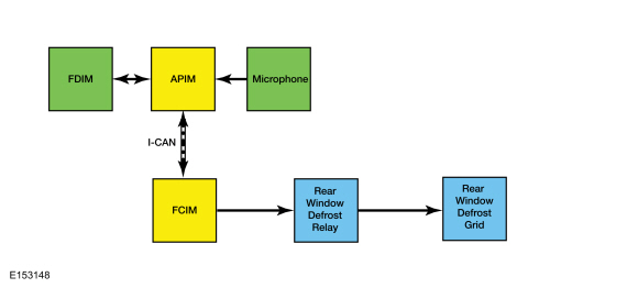
System Diagram - Rear Window Defrost
Network Message Chart - Rear Window Defrost
Front Controls Interface Module (FCIM) Network Input Messages
| Broadcast Message | Originating Module | Message Purpose |
|---|---|---|
| Climate control requests | APIM (if equipped with touchscreen) | The climate control requests message contains the rear window defrost request information. When the rear window defrost function is requested using voice command or the button is selected on the touchscreen, this input activates the rear window defrost system. |
Power Window Operation - Front
NOTE: If the vehicle battery is disconnected while the window is moving, the one-touch up and one-touch down feature (and obstacle detection) is disabled prior to initialization.
Refer to: Power Door Window Initialization (501-11 Glass, Frames and Mechanisms, General Procedures).
The power windows operate when the delayed accessory relay is active. The delayed accessory relay (non-serviceable) is located in the BCM. Both front windows are equipped with obstacle detection and one-touch up and one-touch down functionality. If an obstacle has been detected as the window glass is moving upward, the window motor automatically reverses direction and moves the glass downward.
Driver Door Window Operation
The driver door window control switch communicates to the DDM through a LIN. When commanded by the driver door window control switch, the DDM supplies power and ground to operate the driver door window regulator motor in the desired direction. The DDM monitors the window glass position through feedback from 2 Hall-effect sensors (integral to the driver door window regulator motor). If there is an issue with the Hall-effect sensor circuit(s), the DDM only moves the window in 500 ms intervals (the driver door window control switch must be released and activated again to move the window).
Passenger Door Window Operation
The driver door window control switch communicates to the DDM through a LIN. The DDM communicates to the PDM through the Medium Speed Controller Area Network (MS-CAN).
When commanded by the driver door window control switch or the passenger door window control switch, the PDM supplies power and ground to operate the passenger door window regulator motor in the desired direction. The PDM monitors window glass position through feedback from 2 Hall-effect sensors (integral to the passenger door window regulator motor). If there is an issue with the Hall-effect sensor circuit(s), the PDM only moves the window in 500 ms intervals (the passenger or driver door window control switch must be released and activated again to move the window).
Rear Door Window Operation
NOTE: If the vehicle battery is disconnected while the window is moving, the one-touch up and one-touch down feature (and obstacle detection) is disabled prior to initialization.
Refer to: Power Door Window Initialization (501-11 Glass, Frames and Mechanisms, General Procedures).
Both rear door windows are equipped with obstacle detection and one-touch up and one-touch down functionality. If an obstacle has been detected in the window opening as the window glass is moving upward, the window motor automatically reverses direction and moves the glass downward.
Driver Side Rear Door Window Operation
The driver door window control switch communicates to the DDM through a LIN. The DDM communicates to the RDM through a LIN.
When commanded by the driver door window control switch or the rear door window control switch, the RDM supplies power and ground to operate the rear door window regulator motor in the desired direction. The RDM monitors window glass position through feedback from 2 Hall-effect sensors (integral to the rear door window regulator motor). If there is an issue with the Hall-effect sensor circuit(s), the RDM only moves the window in 500 ms intervals (the driver or rear door window control switch must be released and activated again to move the window).
Passenger Side Rear Door Window Operation
The driver door window control switch communicates to the DDM through a LIN. The DDM communicates to the PDM through the Medium Speed Controller Area Network (MS-CAN). The PDM communicates to the RDM through a LIN.
When commanded by the driver door window control switch or the rear door window control switch, the RDM supplies power and ground to operate the rear door window regulator motor in the desired direction. The RDM monitors window glass position through feedback from 2 Hall-effect sensors (integral to the rear door window regulator motor). If there is an issue with the Hall-effect sensor circuit(s), the RDM only moves the window in 500 ms intervals (the driver or rear door window control switch must be released and activated again to move the window).
Passenger Windows Lock-Out
When the lock-out switch (part of the driver door window control switch) is in the LOCK position, the rear door passenger power windows can be operated from the driver door window control switch.
Global Open/Close
NOTE: The global open/close feature may be enabled/disabled by the customer following a procedure listed in the Owner's Literature. For a complete list of available programmable parameters, refer to Module Configuration in Section 418-01.
The global open/close feature only activates when the ignition is off and the delayed accessory relay is not active. When the unlock button on the RKE transmitter is pressed and held, the windows begin opening and the roof opening panel (if equipped) moves to the VENT position. Pressing and holding the lock button on the RKE transmitter begins closing the windows and roof opening panel (if equipped).
Rear Window Defrost
When the rear window defrost switch (integral to the FCIM) is activated, the FCIM activates the rear window defrost relay (integral to the BJB).
If equipped, the rear window defrost can also be commanded on and off using voice commands or by touching the rear window defrost button located on the touchscreen interface (FDIM). For additional information on voice or touchscreen commanded features, refer to the Owner's Literature.
The FCIM deactivates the rear window defrost relay when one of these conditions is met:
- The rear window defrost switch is pressed when the feature is active.
- If equipped, the rear window defrost is commanded off using voice command or the touchscreen interface when the feature is active.
- Ignition state is changed from ON to OFF.
- A predetermined timer completes.
- Battery voltage has dropped below a specified threshold (load management strategy).
Remote Start - Rear Window Defrost Operation
The customer can select different climate control modes/preferences when the vehicle is started using the remote start feature. This can be accessed through the message center. For additional information on setting the remote start preferences, refer to the Owner's Literature. When the rear defrost is set to AUTO mode, the rear window defrost activates when the outside temperature is less than 0°C (32°F) and the vehicle is started using the remote start feature. No climate control adjustments are recognized during remote start operation. Once the ignition is cycled to the ON position, the climate control system returns to the previous settings (last ignition ON cycle) and adjustments can be made normally. If the previous setting was off, the climate control system turns off.
Component Description
Driver Door Window Control Switch
The driver door window control switch receives voltage whenever the delayed accessory relay is active. The driver door window control switch is grounded through the DDM. The driver door window control switch communicates to the DDM through a LIN.
Passenger Door Window Control Switch
The passenger door window control switch contains momentary contacts (one for each window switch direction). The PDM provides a return (ground) for the passenger door window control switch. When the control switch is activated, a ground signal is supplied to the PDM to operate the passenger door window regulator motor in the desired direction.
Rear Door Window Control Switch
Each of the rear door window control switches contains momentary contacts (one for each window switch direction). The driver or passenger side RDM provides a return (ground) for the rear door window control switch. When the rear door window control switch is activated, a ground signal is supplied to the driver or passenger side RDM to operate the rear door window regulator motor in the desired direction.
Door Window Regulator Motor
The door window regulator motor(s) are bi-directional. Window direction is determined by the polarity of the voltage being supplied to the motor from the associated door module. The door window regulator motor contains 2 Hall-effect sensors. The Hall-effect sensor power supply and return circuits are provided by the associated door module.
Front Controls Interface Module (FCIM)
The FCIM contains the rear window defrost button and also controls the rear window defrost relay.
Front Display Interface Module (FDIM)
The FDIM contains a redundant rear window defrost button on the touchscreen display. The FDIM plugs directly into the APIM, and does not communicate directly on any network.
Driver Door Module (DDM)
The DDM receives power window commands from the driver door window control switch through a LIN. The DDM supplies voltage and ground to operate the driver door window regulator motor.
The DDM also communicates driver door window control switch requests to the associated RDM through a LIN and to the PDM through the Medium Speed Controller Area Network (MS-CAN).
Passenger Door Module (PDM)
The PDM receives power window commands from the passenger door window control switch or from the DDM through the Medium Speed Controller Area Network (MS-CAN). The PDM supplies voltage and ground to operate the passenger door window regulator motor.
The PDM also communicates driver door window control switch requests to the passenger RDM through a LIN.
Rear Door Module (RDM)
The driver side RDM receives power window commands from the rear door window control switch or from the DDM through a LIN. The RDM supplies voltage and ground to operate the rear door window regulator motor.
The passenger side RDM receives power window commands from the rear door window control switch or from the PDM through a LIN. The RDM supplies voltage and ground to operate the rear door window regulator motor.
 Glass, Frames and Mechanisms - Overview. Description and Operation
Overview
Power Windows
Standard power window features include one-touch up and one-touch down operation.
The window control switch:
can be used to manually or automatically raise/lower all
windows from the driver door window control switch or the individual
passenger window from the corresponding door switch...

Other information:
Ford Fusion 2013–2020 Service Manual: Anti-Lock Brake System (ABS) Module. Removal and Installation
Removal NOTE: Removal steps in this procedure may contain installation details. NOTE: The ABS module and HCU are released individually. A new ABS module does not come equipped with an HCU. NOTE: The PMI process must begin with the current ABS module installed. If the current ABS module does not respond to the diagnostic scan tool, the tool may prompt for As-Built Data as part of..
Ford Fusion 2013–2020 Service Manual: Roof Opening Panel. Diagnosis and Testing
The roof opening panel motor must be initialized when repairs are carried out on any part of the roof opening panel system or when the roof opening panel motor, glass, assembly, or air deflector has been removed or replaced for any reason. Symptom Charts Symptom Chart: Operation Diagnostics in this manual assume a certain skill level and knowledge of Ford-specific diagnostic practice..
Categories
- Manuals Home
- 2nd Generation Ford Fusion Owners Manual
- 2nd Generation Ford Fusion Service Manual
- Intake Manifold. Removal and Installation
- Main Control Valve Body. Removal and Installation
- Steering Column Control Module (SCCM). Removal and Installation
- New on site
- Most important about car
Child Safety Locks
When these locks are set, the rear doors cannot be opened from the inside.
