Ford Fusion: Anti-Lock Brake System (ABS) and Stability Control / Anti-Lock Brake System (ABS) Module. Removal and Installation
Removal
NOTE: Removal steps in this procedure may contain installation details.
NOTE: The ABS module and HCU are released individually. A new ABS module does not come equipped with an HCU.
-
NOTE: The PMI process must begin with the current ABS module installed. If the current ABS module does not respond to the diagnostic scan tool, the tool may prompt for As-Built Data as part of the repair.
Using a diagnostic scan tool, begin the PMI process for the ABS module following the on-screen instructions.
-
Remove the HCU.
Refer to: Hydraulic Control Unit (HCU) (206-09 Anti-Lock Brake System (ABS) and Stability Control, Removal and Installation).
-
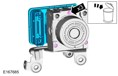
NOTICE: Make sure the HCU and ABS module are clean and free of brake fluid or foreign material before separating the components. Do not allow any brake fluid or foreign material to enter the mating side of the ABS module or component damage can occur.
Remove the screws and the ABS module. Discard the screws.
Torque: 49 lb.in (5.5 Nm)
 |
Installation
-
To install, reverse the removal procedure.
-
Using a diagnostic scan tool, complete the PMI process for the ABS module following the on-screen instructions.
 Rear Wheel Speed Sensor. Removal and Installation
Removal
NOTE:
Removal steps in this procedure may contain installation details.
All vehicles
With the vehicle in NEUTRAL, position it on a hoist...

Other information:
Ford Fusion 2013–2020 Service Manual: Pyrotechnic Device Health and Safety Precautions. Description and Operation
WARNING: Service and handling of Pyrotechnic Components is restricted to qualified personnel. The required qualifications vary by region. Always observe local laws and legislative directives regarding Pyrotechnic Components service and handling. Failure to follow this instruction may result in serious personal injury or death. WARNING: Always carry a live airbag with t..
Ford Fusion 2013–2020 Service Manual: Glove Compartment. Removal and Installation
Special Tool(s) / General Equipment Interior Trim Remover Removal NOTE: Removal steps in this procedure may contain installation details. WARNING: Before beginning any service procedure in this section, refer to Safety Warnings in section 100-00 General Information. Failure to follow this instruction may result in serious personal injury. Refer to: Health a..
Categories
- Manuals Home
- 2nd Generation Ford Fusion Owners Manual
- 2nd Generation Ford Fusion Service Manual
- Under Hood Overview - 1.5L EcoBoost™, 2.0L EcoBoost™, 2.5L, 2.7L EcoBoost™
- Automatic Transmission Fluid Check - 1.5L EcoBoost™/2.0L EcoBoost™/2.5L. Automatic Transmission Fluid Check - 2.7L EcoBoost™
- Main Control Valve Body. Removal and Installation
- New on site
- Most important about car
Power Door Locks
The power door lock control is on the driver and front passenger door panels.