Ford Fusion: Instrument Panel and Console / Floor Console. Removal and Installation
Ford Fusion 2013–2020 Service Manual / Body and Paint / Body and Paint / Instrument Panel and Console / Floor Console. Removal and Installation
Special Tool(s) / General Equipment
| Interior Trim Remover |
Removal
NOTE: Removal steps in this procedure may contain installation details.
-
Refer to: Health and Safety Precautions (100-00 General Information, Description and Operation). WARNING:
Before beginning any service procedure in this
section, refer to Safety Warnings in section 100-00 General Information.
Failure to follow this instruction may result in serious personal
injury.
WARNING:
Before beginning any service procedure in this
section, refer to Safety Warnings in section 100-00 General Information.
Failure to follow this instruction may result in serious personal
injury.
-
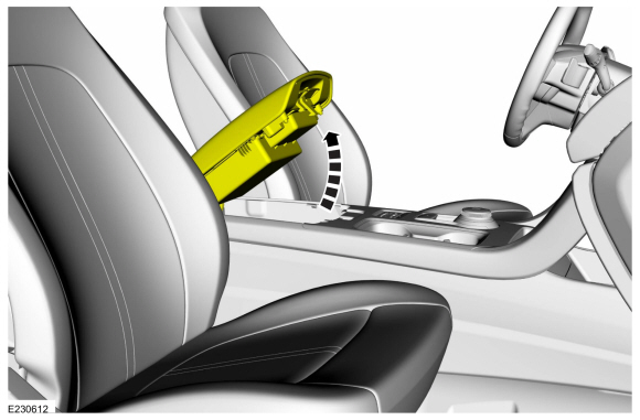
Open the floor console armrest.
 |
-
NOTE: RH side shown, LH side similar.
On both sides.
Release the clips and remove the floor console upper finish panel.
Use the General Equipment: Interior Trim Remover
 |
-
Release the clips, remove the screws and remove the the floor console upper trim panel.
-
Disconnect the electrical connectors.
Use the General Equipment: Interior Trim Remover
-
Disconnect the electrical connectors.
 |
-
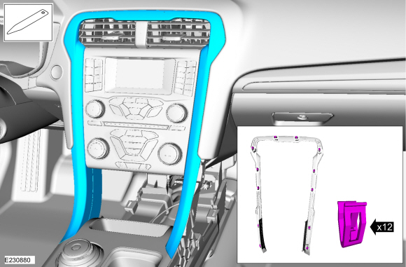
Remove the center stack trim panel.
Use the General Equipment: Interior Trim Remover
 |
-
NOTE: RH side shown, LH side similar.
On both sides.
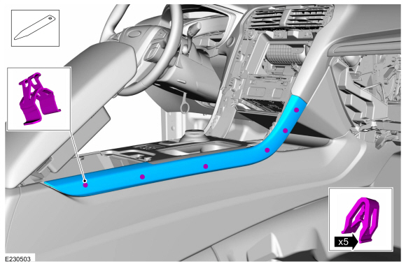
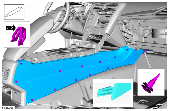
Release the push pin, clips starting from front to rear. Disengage the finger tab at the bottom rear corner and remove the floor console side trim panel.
Use the General Equipment: Interior Trim Remover
 |
-
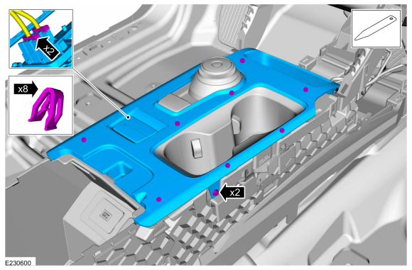
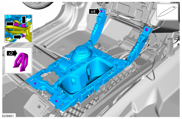
Release the clips, remove the bolts and remove the floor console upper finish panel.
-
Disconnect the electrical connector.
Use the General Equipment: Interior Trim Remover
-
Disconnect the electrical connector.
 |
-
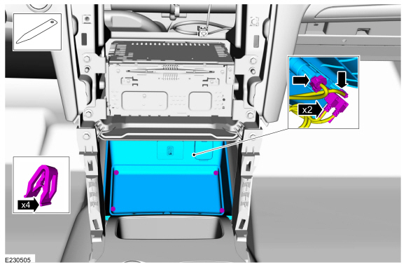
Release the clips and remove the lower center instrument panel storage bin.
-
Disconnect the electrical connectors.
Use the General Equipment: Interior Trim Remover
-
Disconnect the electrical connectors.
 |
-
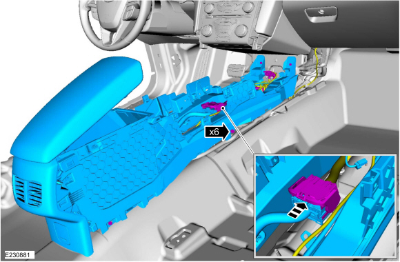
Disconnect the electrical connectors, remove the bolts and the floor console.
Torque: 55 lb.in (6.2 Nm)
 |
Installation
-
To install, reverse the removal procedure.
-
NOTE: Anytime the parking brake switch electrical connector has been disconnected, the EPB system is deactivated and a DTC is stored in the ABS module. Perform the following step to restore the EPB system and clear the ABS module DTC.
Apply and release the parking brake twice within 5 seconds, pausing with the switch in the NEUTRAL position for approximately one-half second between each apply and release.
 Auxiliary Power Point. Removal and Installation
Special Tool(s) /
General Equipment
501-039Remover, Power Point SocketTKIT-1998-FLMTKIT-1998-LM
Removal
WARNING:
Before beginning any service procedure in this
section, refer to Safety Warnings in section 100-00 General Information...
 Glove Compartment. Removal and Installation
Special Tool(s) /
General Equipment
Interior Trim Remover
Removal
NOTE:
Removal steps in this procedure may contain installation details...
Other information:
Ford Fusion 2013–2020 Service Manual: Engine Undershield. Removal and Installation
Remove the screws, grommets and the engine front undershield. Remove the screws and the engine undershield. ..
Ford Fusion 2013–2020 Service Manual: Bearing Inspection. General Procedures
Inspection Cratering - fatigue failure Spot glazing - incorrect seating Scratching - dirty engine oil Base exposed - poor lubrication Both edges worn - journal damaged One edge worn - journal tapered or bearing not seated ..
Categories
- Manuals Home
- 2nd Generation Ford Fusion Owners Manual
- 2nd Generation Ford Fusion Service Manual
- Front Controls Interface Module (FCIM). Removal and Installation
- Cylinder Head. Removal and Installation
- Starter Motor. Removal and Installation
- New on site
- Most important about car
Child Safety Locks
When these locks are set, the rear doors cannot be opened from the inside.

Copyright © 2026 www.fofusion2.com