Ford Fusion: Charging System - General Information / Charging System - System Operation and Component Description. Description and Operation
System Operation
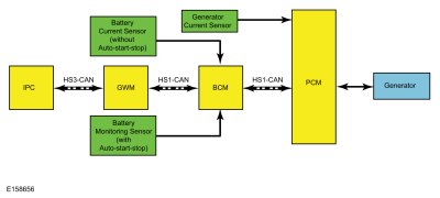
System Diagram
Network Message Chart
Module Network Input Messages — Body Control Module (BCM)
| Broadcast Message | Originating Module | Message Purpose |
|---|---|---|
| Alternator fault | PCM | The PCM has detected a fault in the generator or generator circuits. |
Module Network Input Messages — Instrument Panel Cluster (IPC)
| Broadcast Message | Originating Module | Message Purpose |
|---|---|---|
| Power system status | BCM | Reports any generator/charging system faults. Used for charging system fault indicator. |
| Load Shed Request | BCM | Used to indicate what level of load shed is commanded. |
Module Network Input Messages — Powertrain Control Module (PCM)
| Broadcast Message | Originating Module | Message Purpose |
|---|---|---|
| Load Shed Request | BCM | Used to indicate what level of load shed is commanded. |
Charging System
The PCM-controlled, or Smart Charge charging system determines the optimal voltage setpoint for the charging system and communicates this information to the voltage regulator. The Smart Charge charging system sets Diagnostic Trouble Codes (DTCs) when a charging system fault is present. All of the Diagnostic Trouble Codes (DTCs) can set continuous faults, but not all Diagnostic Trouble Codes (DTCs) set as on-demand faults.
This system uses 2 communication lines between the PCM and the generator/voltage regulator. Both of these communication lines use PWM. The generator communication (GENCOM) line communicates the desired setpoint from the PCM to the voltage regulator. The generator monitor (GENMON) line communicates the generator load and error conditions to the PCM. The PCM sends the GENCOM command only when it is necessary to adjust the voltage setpoint. If the setpoint does not need to be changed, several seconds may elapse between PCM GENCOM commands. This normal operation appears in the PID as occasional bursts of pulse-width commands. The third pin on the voltage regulator, the "A" circuit pin, is a circuit dedicated to monitor or sense battery voltage.
The PCM simultaneously controls and monitors the generator output. When the current consumption is high or the battery is discharged, the PCM raises engine speed as needed to increase generator output. The generator charges the battery and at the same time supplies power for all required electrical loads. The battery is more effectively charged with a higher voltage when the battery is cold and a lower voltage when the battery is warm. The PCM uses a signal from the IAT sensor to adjust the charging voltage according to the battery temperature. The PCM also uses other inputs to control the charging system voltage such as the VSS and engine coolant temperature. The voltage setpoint is calculated by the PCM and communicated to the voltage regulator by the GENCOM circuit based on the needs of the vehicle and the conditions.
The PCM turns off the generator during cranking to reduce the generator load and improve cranking speed. Once the engine starts, the PCM slowly increases generator output to the desired voltage.
The PCM reports any charging system faults and sends a message through the High Speed Controller Area Network (HS-CAN) to the BCM. The BCM controls the charging system warning indicator by sending a message over the Medium Speed Controller Area Network (MS-CAN) to the IPC . The IPC then controls charging system warning indication based on the message from the PCM through the BCM. The status of the PCM charging system warning indicator and/or message is confirmed by viewing PCM PID generator fault indicator lamp (GENFIL). Any charging system fault detected by the PCM results in 1 or more Diagnostic Trouble Codes (DTCs) being set and the PID GENFIL having a status of On. If equipped with a charging system warning indicator, the IPC turns the indicator on or off. If equipped with a message center, the IPC displays a CHECK CHARGING SYSTEM message. In some instances, the CHECK CHARGING SYSTEM message may not display if the ignition is ON and the engine is off.
Under certain circumstances, the charging system may have a concern, but will still keep the battery charged and the vehicle running. GENCOM normally initiates charging, but the generator may charge with a fault in this circuit. If the engine operates at more than 2,000 RPM momentarily, the generator may self-excite and start charging on its own. The charging system warning indicator is illuminated and/or CHECK CHARGING SYSTEM message is displayed, and the generator operates in a default mode (approximately 13.5 volts) until the engine is turned off. When the engine is restarted and the engine operates at more than 2,000 RPM momentarily, the generator may again self-excite and again the charging system warning indicator is illuminated and/or CHECK CHARGING SYSTEM message is displayed.
Electrical Energy Management
NOTICE: When any vehicle module is being programmed, connect an external battery charger to make sure the module programming is completed without interruption due to the load shedding feature becoming active. The external battery charger must maintain a system voltage above 13 volts. This may require a charger setting higher than the lowest charge setting. The external battery charger negative connection must be made to an engine or vehicle chassis ground and not the negative battery terminal. If the connection is to the negative battery terminal, load shedding may begin and module programming may be corrupted. After charging has begun, start the engine to clear any load shed states and then turn the engine off and proceed with programming.
The Electrical Energy Management system software is housed in the BCM. It has the algorithms and control structure for the Auto-Stop-Start Function (if equipped), Smart Regenerative Charging, and Load Shed Control Strategy. The Electrical Energy Management system is equipped with 2 unique sensors to monitor the battery depending on the vehicle system features / operation.
- Battery Monitoring Sensor (Auto-Start-Stop)
- Battery Current Sensor (Without Auto-Start-Stop)
These sensors serve as input to the Electrical Energy Management software. If the sensors malfunction due to wiring issues or failure, a DTC will be set. In most cases the Electrical Energy Management functions will be turned off until the sensor operation is restored.
Battery State of Charge
During the drive cycle the Electrical Energy Management software will adjust the initial battery state of charge by monitoring the charge and discharge current and adjusting the state of charge up during charging, and down during discharge. During rest periods (key off with no electrical loads) when the vehicle enters sleep mode, the battery voltage is sampled to recalibrate the State of Charge. The sensor automatically executes this recalibration anytime the vehicle enters sleep mode and when the total vehicle current draw is below 300mA. It takes 4 to 6 hours in the sleep mode to recalibrate the battery state of charge to high accuracy. If the system draw does not allow the battery state of charge recalibration over the previous 7 to 10 days the State of Charge quality factor will change to flag this and some Electrical Energy Management Functions which rely on the accuracy of the battery state of charge may be temporarily turned off until a recalibration takes place.
NOTE: Any devices left attached to the power socket that draw in excess of 200mA (or less depending on other battery loads) will prevent a battery monitoring sensor to recalibrate the battery state of charge.
Engine Off Load Shed
The BCM uses the battery current sensor to keep track of the battery state of charge. The battery current sensor is a Hall-effect sensor attached to the battery ground cable. When the engine is off and the BCM determines the battery state of charge is below 50%, or 45 minutes have elapsed, a load shed message is sent over the CAN. This message turns off the audio/navigation system to save the remaining battery charge. Under this condition the FCDIM (without touchscreen controls) displays System Off to Save Battery Turn Ignition Off, or the FDIM (with touchscreen controls) displays SYSTEM OFF TO SAVE BATTERY PLEASE TURN IGNITION OFF OR START ENGINE to notify the driver that battery protection actions are active.
Engine off load shedding occurs when the engine is not running and the ignition is in the ACC, RUN or delayed accessory position. This load shed state clears once the vehicle has been started and the battery state of charge recovers. If the engine off load shed occurs, the audio/navigation system turns off.
When the ignition is in the RUN position and if load shed occurs, the IPC message center may display either TURN POWER OFF TO SAVE BATT (base message center) or TURN POWER OFF TO SAVE BATTERY (optional message center). The audio/navigation system shuts down after the message center displays the warning.
If a fault occurs with the battery current sensor or circuit(s), the only engine off load shed strategy that is active is a 45 minute timer. After 45 minutes have elapsed, the audio/navigation system turns off. To clear the load shed state, restart the engine.
When
the ignition is in the OFF position or Ignition key removed
Infotainment extended play can be enabled. When Infotainment extended
play is enabled and a load shed message is received over CAN the
extended play will turn off to save the remaining battery charge. Under
this condition FCDIM will display SYSTEM OFF TO SAVE BATTERY to notify the driver that battery protections are active. For more information,
Refer to: Message Center - System Operation and Component Description (413-01 Instrumentation, Message Center and Warning Chimes, Description and Operation).
Engine Running Load Shed
When the BCM and/or PCM voltage is low, with the engine running, the BCM sends a message to either minimize or shut down the climate controlled seats, rear defrost, heated mirrors and climate control blower motor to improve system voltage. Under this condition, the IPC message center displays LOW BATTERY FEATURES TEMPORARILY TURNED OFF to notify the driver that battery protection actions are active during a Load Shed 2 continuous event.
There are 3 states of engine running load shed:
| Load Shed State | Entry Conditions | Impact to Features | Clear Conditions |
| Load shed 1 | Alternator at full load and battery discharging while driving. System voltage less than 11.5 volts | Incrementally reduce loads If equipped: Heated Steering Wheel, Smart Trailer Tow Battery Charge will turn Off, Climate controlled seats, Heated Mirrors and Heated Backglass will turn Off, Heated Windscreen will turn Off | System operating at normal power level. |
| Load shed 2 transient | EPAS indicating reduced voltage and increased current. System voltage less than 11 volts | Turn Off Loads without customer indication. If equipped, Heated Steering Wheel, Smart Trailer Tow Battery Charge, Climate controlled seats, Heated Mirrors and Heated Backglass, Heated Windscreen | System operating at normal power level. |
| Load shed 2 continuous | Load Shed 2 Transient condition in excess of 20 seconds | In addition to Load Shed 2 Transient turn off If equipped, 110 Volt Inverter, Heated Windscreen, Climate Control Blower (reduced speed less FMVSS required operation). During Load Shed 2 Continuous feature on indication will turn off for Heated Steering Wheel, Climate Controlled Seats, Heated Mirrors and Heated Backglass. | System operating at normal power level. |
Battery Charging
When it is required to charge the vehicle battery, connect the positive connection to the battery positive post, and place the charger negative to vehicle ground. Do not connect the negative cable of the charger to the battery negative terminal. Connecting directly to the battery negative post bypasses the vehicle sensors, not allowing the battery current sensor or the battery monitoring sensor to detect the charge current. As a result the battery state of charge does not reflect the charging. Look for the body ground cable coming off the clamp or the battery monitoring sensor and try and connect in this location (typically on the shock tower sheet metal). The placement of the battery is such that the battery negative terminal is located under the sheet metal shroud making sheet metal ground the obvious choice for the charger.
If the vehicle is equipped with the Auto-start-stop system, it is equipped with a battery monitoring sensor. If the battery is replaced, perform the battery monitoring system reset using the diagnostic scan tool. If the vehicle battery is charged by connecting the battery charger to the battery negative terminal it takes approximately 8 hours for the BCM to learn the new battery state of charge. If the vehicle is used before the BCM is allowed to learn the new battery state of charge, the Auto-start-stop system may not operate.
NOTE: If the vehicle is equipped with the Auto-start-stop system, and it has been determined that the function is inhibited due to a low battery state of charge (less than 70%), it is critical that the battery charger connection be made correctly to increase the State of Charge. If it is improperly connected the inhibit will not be removed. If you fully charge the battery incorrectly and bypass the Battery Monitor Sensor, and you would like to remove the auto-start-stop inhibit for the customer, you can open the battery positive connection wait 10 seconds and reconnect the battery positive. This triggers a “quick state of charge algorithm” within the battery monitoring sensor which estimates the State of Charge, and if the battery has been sufficiently charged, the inhibit for low State of Charge is removed and the Auto-start-stop function is restored.
If the battery is being charged due to a load shedding message, only charging the battery properly assists in clearing this message. The Electrical Energy Management will recalibrate the battery state of charge as described above after about 8 hours if the charger was improperly installed.
NOTICE: If the charger is incorrectly connected to the battery negative terminal, DO NOT reset the battery monitoring system using the diagnostic scan tool. This reset is reserved only for new battery installation. This reset will clear the learned battery data, the battery time in service, and will affect the aging algorithm parameters, which have been learned since the installation of the battery.
Jump Starting
When it is required to jump start the vehicle, just like battery charging, it is important to connect the cables properly for the Electrical Energy Management system to measure the energy input to the system to keep an accurate State of Charge. Connect the positive connection to the battery positive post, and connect the Jump Start negative to the vehicle ground. Do not connect to the negative battery terminal. Connecting directly to the battery negative post bypasses the ability of the vehicle to measure the input current with the Battery Current Sensor or the battery monitoring sensor, and does not adjust the battery state of charge accordingly. For a convenient ground location look for the body ground cable coming off the clamp or the Battery Monitor Sensor and try and connect in this location (typically on the shock tower sheet metal). The Electrical Energy Management will recalibrate the battery state of charge as described above after about 8 hours if the jump start negative cable is improperly installed.
NOTICE: If the charger is incorrectly connected to the battery negative terminal, DO NOT reset the battery monitoring system using the scan tool. This reset is reserved only for new battery installation. This reset will clear the learned battery data, the battery time in service, and will affect the aging algorithm parameters, which have been learned since the installation of the battery.
Battery Replacement
If
the vehicle battery is replaced, it is very important to perform the
battery monitoring system reset using the scan tool. If the battery
monitoring system reset is not carried out, it holds the old battery
parameters and time in service counter in memory. Additionally it tells
the system the battery is in an aged state and the may limit the
Electrical Energy Management system functions. For more information,
Refer to: Battery and Cables - System Operation and Component Description (414-01 Battery, Mounting and Cables, Description and Operation).
Component Description
Generator
The generator is equipped with an electronic internal voltage regulator and a serviceable generator clutch pulley.
Generator Current Sensor
The generator current sensor is attached to the generator B+ cable. It is supplied a 5-volt reference voltage and a ground from the PCM. The generator current sensor is a Hall-effect sensor that supplies an analog feedback signal to the PCM.
Battery Current Sensor
NOTE: Vehicles with Auto-Start-Stop are not equipped with a battery current sensor.
If the vehicle has Smart Regenerative Function / Load shed strategy it will have a battery current sensor, which is installed over the battery ground cable. It is supplied a 5-volt reference voltage and a ground from the BCM. The battery current sensor is a Hall-effect sensor that supplies a PWM feedback signal to the BCM. These sensors serve as input to the Electrical Energy Management software. If the sensors malfunction due to wiring issues or failure a DTC will be set. In most cases the Electrical Energy Management functions are turned off until the sensor operation is restored.
Battery Monitoring Sensor
NOTE: Only vehicles with Auto-Start-Stop are equipped with a battery monitoring sensor.
The battery monitoring sensor is integrated with the negative battery terminal clamp and cable assembly, which provides a ground to the sensor. The battery monitoring sensor measures voltage, current, and temperature of the battery and uses these inputs to calculate the battery condition. The sensor transmits this information through the LIN circuit to the BCM. The battery monitoring sensor has a 2-pin connector providing battery voltage and LIN connections.
Powertrain Control Module (PCM)
The PCM monitors and controls the charging system.
Generator Clutch
The generator clutch is serviced separately from the generator. The primary function is to separate the generator rotor inertia from the FEAD belt, lowering belt tension at high Revolutions Per Minute (RPM) and reducing NVH.
 Charging System - Overview. Description and Operation
Overview
The generator is driven by the FEAD belt. When the engine is started, the generator begins to generate AC voltage which is internally converted to DC voltage...
 Charging System. Diagnosis and Testing
Inspection and Verification
Verify the customer concern by operating the charging system.
Before diagnosing or repairing the charging system inspect the following items:
Check the battery for loose, damaged or corroded connections...
Other information:
Ford Fusion 2013–2020 Service Manual: Front Bumper Cover. Removal and Installation
Removal NOTE: Removal steps in this procedure may contain installation details. Remove the front wheels and tires. Refer to: Wheel and Tire (204-04A Wheels and Tires, Removal and Installation). On both sides. Remove the rivet push pin and the screws from the front of the fender liner...
Ford Fusion 2013–2020 Service Manual: Rear Floor Panel. Removal and Installation
Special Tool(s) / General Equipment Resistance Spotwelding Equipment Scraper for Straight Edges Hot Air Gun 8 mm Drill Bit MIG/MAG Welding Equipment Spot Weld Drill Bit Locking Pliers Materials Name Specification Seam SealerTA-2-B, 3M™ 08308, LORD Fusor® 803DTM - Removal NOTICE: Battery electric vehicle (BEV), hybrid electric ve..
Categories
- Manuals Home
- 2nd Generation Ford Fusion Owners Manual
- 2nd Generation Ford Fusion Service Manual
- Traction Control
- Memory Function
- Intake Manifold. Removal and Installation
- New on site
- Most important about car
Direction Indicators. Interior Lamps
Direction Indicators

Push the lever up or down to use the direction indicators.