Ford Fusion: Rear Suspension / Upper Arm. Removal and Installation
Special Tool(s) / General Equipment
| Vehicle/Axle Stands |
Removal
NOTICE: Suspension fasteners are critical parts that affect the performance of vital components and systems. Failure of these fasteners may result in major service expense. Use the same or equivalent parts if replacement is necessary. Do not use a replacement part of lesser quality or substitute design. Tighten fasteners as specified.
NOTE: Removal steps in this procedure may contain installation details.
-
Remove the wheel and tire.
Refer to: Wheel and Tire (204-04 Wheels and Tires) .
-
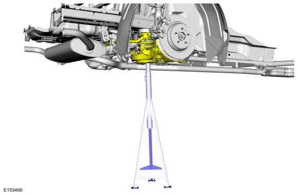
Support the rear suspension to ride height.
Use the General Equipment: Vehicle/Axle Stands
 |
-
NOTICE: Tighten the suspension bushing fasteners with the suspension loaded or with the weight of the vehicle resting on the wheels and tires, otherwise incorrect clamp load and bushing damage may occur.
-
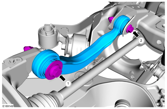
Remove the upper arm-to-wheel knuckle bolt and nut.
Torque: 136 lb.ft (185 Nm)
-
Remove the upper arm-to-rear subframe bolt and nut, remove the upper arm.
Torque: 76 lb.ft (103 Nm)
-
Remove the upper arm-to-wheel knuckle bolt and nut.
 |
Installation
-
To install, reverse the removal procedure.
-
Check and if necessary adjust rear camber.
Refer to: Rear Camber Adjustment (204-00 Suspension System - General Information, General Procedures).
 Rear Stabilizer Bar Link. Removal and Installation
Removal
NOTE:
Removal steps in this procedure may contain installation details.
With the vehicle in NEUTRAL, position it on a hoist.
Refer to: Jacking and Lifting - Overview (100-02 Jacking and Lifting, Description and Operation)...
 Lower Arm. Removal and Installation
Special Tool(s) /
General Equipment
Vehicle/Axle Stands
Removal
NOTICE:
Suspension fasteners are critical parts that affect the
performance of vital components and systems...
Other information:
Ford Fusion 2013–2020 Service Manual: Charge Air Cooler (CAC) Radiator. Removal and Installation
Special Tool(s) / General Equipment Cable Ties Hose Clamp Remover/Installer Removal NOTE: Removal steps in this procedure may contain installation details. Remove the retainers and the radiator sight shield. Remove the upper radiator guide pins and support the radiator using cable ties...
Ford Fusion 2013–2020 Service Manual: Variable Camshaft Timing (VCT) Oil Control Solenoid. Removal and Installation
Removal NOTE: Removal steps in this procedure may contain installation details. Remove the engine appearance cover. Disconnect the electrical connectors, remove the bolts and the VCT oil control solenoids...
Categories
- Manuals Home
- 2nd Generation Ford Fusion Owners Manual
- 2nd Generation Ford Fusion Service Manual
- Load Carrying
- Main Control Valve Body. Removal and Installation
- Starter Motor. Removal and Installation
- New on site
- Most important about car
Cross Traffic Alert System Sensors
The sensors are behind the rear bumper on both sides of your vehicle.