Ford Fusion: Charging System - General Information / Charging System. Diagnosis and Testing
Inspection and Verification
-
Verify the customer concern by operating the charging system.
-
Before diagnosing or repairing the charging system inspect the following items:
-
Check the battery for loose, damaged or corroded connections.
-
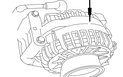
Check the generator for loose, damaged or corroded connections.
-
Check engine and battery grounds for loose, damaged or corroded connections.
-
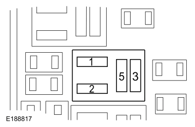
Check high current BJB for loose or corroded connections.
-
Verify fuses or fusible links.
-
Inspect wiring, terminals and connectors.
-
Inspect the FEAD system. For 1.5L EcoBoost,
REFER to: Accessory Drive (303-05A Accessory Drive - 1.5L EcoBoost (118kW/160PS) – I4, Diagnosis and Testing).
For 2.0L EcoBoost, REFER to: Accessory Drive (303-05B Accessory Drive - 2.0L EcoBoost (184kW/250PS) – MI4, Diagnosis and Testing).
For 2.5L Duratec, REFER to: Accessory Drive (303-05C Accessory Drive - 2.5L Duratec (125kW/170PS), Diagnosis and Testing).
For 2.7L EcoBoost, REFER to: Accessory Drive (303-05D Accessory Drive - 2.7L EcoBoost (238kW/324PS), Diagnosis and Testing).
-
Check the battery condition and state of charge.
REFER to: Battery (414-01 Battery, Mounting and Cables, Diagnosis and Testing).
-
Check for abnormal ignition-off current drain(s).
REFER to: Battery Drain Check (414-01 Battery, Mounting and Cables, General Procedures).
-
If an obvious cause for an observed or reported concern is found, correct the cause (if possible) before proceeding.
-
Using the diagnostic scan tool, retrieve all Diagnostic
Trouble Codes (DTCs). Refer to the appropriate DTC Chart in this
section.
DTC Charts
Diagnostics in this manual assume a certain skill level and knowledge of Ford-specific diagnostic practices.
REFER to: Diagnostic Methods (100-00 General Information, Description and Operation).
PCM DTC Chart
|
DTC
|
Description
|
Action
|
|
P0562
|
System Voltage Low
|
GO to Pinpoint Test B
|
|
P0563
|
System Voltage High
|
GO to Pinpoint Test A
|
|
P0620
|
Generator Control Circuit
|
GO to Pinpoint Test H
|
|
P0625
|
Generator Field Terminal Circuit Low
|
GO to Pinpoint Test I
|
|
P0626
|
Generator Field Terminal Circuit High
|
GO to Pinpoint Test I
|
|
P065B
|
Generator Control Circuit Range/performance
|
GO to Pinpoint Test H
|
|
P0A5A
|
Generator Current Sensor Circuit Range/Performance
|
GO to Pinpoint Test G
|
|
P0A5B
|
Generator Current Sensor Circuit Low
|
GO to Pinpoint Test G
|
|
P0A5C
|
Generator Current Sensor Circuit High
|
GO to Pinpoint Test G
|
|
P1397
|
System Voltage Out Of Self-Test Range
|
If combined with P0562, GO to Pinpoint Test B If combined with P0563, GO to Pinpoint Test A
|
|
All Other DTCs
|
—
|
For 1.5L EcoBoost, For 2.0L EcoBoost, REFER to: Electronic Engine Controls (303-14B Electronic Engine Controls - 2.0L EcoBoost (184kW/250PS) – MI4, Diagnosis and Testing).
For 2.5L Duratec, REFER to: Electronic Engine Controls (303-14C Electronic Engine Controls - 2.5L Duratec (125kW/170PS), Diagnosis and Testing).
For 2.7L EcoBoost, REFER to: Electronic Engine Controls (303-14D Electronic Engine Controls - 2.7L EcoBoost (238kW/324PS), Diagnosis and Testing).
|
BCM DTC Chart
NOTE:
Diagnose all PCM Diagnostic Trouble Codes (DTCs) first.
|
DTC
|
Description
|
Action
|
|
B11DB:02
|
Battery Monitoring Module "A", General Signal Failure
|
GO to Pinpoint Test F
|
|
B11DB:08
|
Battery Monitoring Module "A", Bus Signal / Message Failure
|
GO to Pinpoint Test F
|
|
B11DB:11
|
Battery Monitoring Module "A", Circuit Short To Ground
|
GO to Pinpoint Test F
|
|
B11DB:49
|
Battery Monitoring Module "A", Internal Electronic Failure
|
CLEAR the Diagnostic Trouble Codes (DTCs). REPEAT the BCM self test. If Diagnostic Trouble Codes (DTCs) B11DB:49 is retrieved, INSTALL new Battery Monitoring Sensor.
REFER to: Battery Monitoring Sensor (414-01 Battery, Mounting and Cables, Removal and Installation).
|
|
B11DB:55
|
Battery Monitoring Module "A", Not Configured
|
CHECK the vehicle service history for recent service actions related to this module. This DTC sets due to incomplete or incorrect PMI
procedures. INSTALL As-Built data from Professional Technician Society
(PTS) following diagnostic scan tool instructions under Module
Programming>As-Built.
|
|
B11DB:9A
|
Battery Monitoring Module "A", Component or System Operating Conditions
|
GO to Pinpoint Test F
|
|
B130C:12
|
Load Shed Control Circuit Short To Battery
|
GO to Pinpoint Test E
|
|
B130C:14
|
Load Shed Control Circuit Short To Ground or Open
|
GO to Pinpoint Test E
|
|
B1438:03
|
Battery Current Sensor, FM / PWM Failure
|
GO to Pinpoint Test E
|
|
B1489:11
|
Battery Monitoring System (BMS) Sensor Power Circuit Short To Ground
|
GO to Pinpoint Test F
|
|
U1007:31
|
Lost Communication With Battery Monitoring Sensor "A": No Signal
|
GO to Pinpoint Test F
|
|
All Other DTCs
|
—
|
REFER to: Body Control Module (BCM) (419-10 Multifunction Electronic Modules, Diagnosis and Testing).
|
Symptom Chart(s)
Symptom Chart: Charging System
Diagnostics in this manual assume a certain skill level and knowledge of Ford-specific diagnostic practices.
REFER to: Diagnostic Methods (100-00 General Information, Description and Operation).
Symptom Chart
|
Condition
|
Possible Sources
|
Actions
|
|
System voltage high
|
Refer to the Pinpoint Test
|
GO to Pinpoint Test A
|
|
System voltage low or battery is discharged
|
Refer to the Pinpoint Test
|
GO to Pinpoint Test B
|
|
The generator is noisy
|
Refer to the Pinpoint Test
|
GO to Pinpoint Test C
|
|
Radio interference
|
Refer to the Pinpoint Test
|
GO to Pinpoint Test D
|
|
Charging system warning indicator is never or always on
|
-
Wiring, terminals or connectors
-
IPC
-
Generator
-
PCM
|
RETRIEVE Diagnostic Trouble Codes
(DTCs) from all modules. If any Diagnostic Trouble Codes (DTCs) are
found, Refer to DTC Chart in this section. If no Diagnostic Trouble
Codes (DTCs) are found,
REFER to: Instrumentation, Message Center and Warning Chimes (413-01 Instrumentation, Message Center and Warning Chimes, Diagnosis and Testing).
|
|
Load Shed Message Displays in IPC message center and/or centerstack infotainment display
|
Refer to the Pinpoint Test
|
GO to Pinpoint Test J
|
|
Battery Saver - System Off displays in centerstack infotainment display
|
Refer to the Pinpoint Test
|
GO to Pinpoint Test J
|
Pinpoint Tests
System Voltage High
Refer to Wiring Diagrams Cell 12 for schematic and connector information.
NOTE:
Diagnostic Trouble Code (DTC)
P0563 can be set if the vehicle has been recently jump started or the
battery has been recently charged. The battery may become discharged due
to excessive load(s) on the charging system from aftermarket
accessories or if vehicle accessories have been operating for an
extended period of time without the engine running.
Normal Operation and Fault Conditions
With
the engine running, the charging system supplies voltage to the battery
and the vehicle electrical system through the high current BJB
and battery B+ cable. The voltage that is supplied to the vehicle
electrical system is used for the operation of the various vehicle
systems and modules. Many modules monitor this voltage and if it rises
above or below their calibrated setpoints, a DTC sets.
Diagnostic Trouble Code (DTC) Fault Trigger Conditions
|
DTC
|
Description
|
Fault Trigger Conditions
|
|
P0563
|
System Voltage High
|
This DTC sets in the PCM when the PCM detects voltage from the charging system greater than 15.9 volts with vehicle speed above 8 km/h (5 mph).
|
|
P1397
|
System Voltage Out of Self-Test Range
|
If the voltage rises above or drops below the calibrated set point, the PCM sets this DTC. This DTC may also be set if the vehicle has been recently jump started or has had a discharged battery.
|
Possible Sources
-
Battery
-
Generator
-
Engine, generator or battery ground
-
PCM
-
Wiring, terminals or connectors
Visual Inspection and Diagnostic Pre-checks
-
Inspect the high current BJB for loose or corroded connections.
PINPOINT TEST A : SYSTEM VOLTAGE HIGH
| NOTE:
Make sure battery voltage is greater than 12.2 volts prior to and during this pinpoint test.
|
| NOTE:
Do not have a battery charger attached during vehicle testing.
|
| A1 PERFORM INSPECTION AND VERIFICATION |
-
Perform Inspection and Verification procedure in this section.
Was an obvious cause for an observed or reported concern found?
| Yes |
CORRECT the cause as necessary.
|
|
| A2 RETRIEVE THE PCM (POWERTRAIN CONTROL MODULE)
DIAGNOSTIC TROUBLE CODES (DTCS) |
-
Using a diagnostic scan tool, perform the PCM self-test.
Is DTC P0620, P0625 or P0626 present?
| Yes |
For DTC P0620, GO to Pinpoint Test H
For Diagnostic Trouble Codes (DTCs) P0625 and P0626, GO to Pinpoint Test I
|
|
| A3 COMPARE THE GENERATOR VOLTAGE DESIRED (GENVDSD) PID (PARAMETER IDENTIFICATION)
WITH BATTERY VOLTAGE |
-
With the engine running at idle, measure and record:
|
Positive Lead
|
Measurement / Action
|
Negative Lead
|

|

|

|
-
Using a diagnostic scan tool, view the PCM
PID GENVDSD.
Is the recorded battery voltage within ±0.5 volt of the PID?
|
| A4 MEASURE THE "A" SENSE VOLTAGE |
-
Disconnect Generator C1558A (2.0L EcoBoost or 2.5L Duratec).
-
Disconnect Generator C102A (All other engines).
-
Measure and record:
|
Positive Lead
|
Measurement / Action
|
Negative Lead
|

|

|

|
-
For the 2.0L EcoBoost or 2.5L Duratec, measure:
Click to display connectors
|
Positive Lead
|
Measurement / Action
|
Negative Lead
|
|
C1558A-3
|

|
Ground
|
-
For all other engines, measure:
Click to display connectors
|
Positive Lead
|
Measurement / Action
|
Negative Lead
|
|
C102A-3
|

|
Ground
|
Is the "A" sense voltage equal to the recorded battery voltage?
| No |
VERIFY high current BJB
fuse 55 (10A) is OK. If OK, REPAIR the circuit. If not OK, REFER to the
Wiring Diagrams manual to identify the possible causes of the circuit
short.
|
|
| A5 "A" SENSE CIRCUIT LOAD TEST |
|
NOTICE:
The following step uses a test light to simulate
normal circuit loads. Use only the test light recommended in the Special
Tools table at the beginning of this section. To avoid connector
terminal damage, use the Flex Probe Kit for the test light probe
connection to the vehicle. Do not use the test light probe directly on
any connector.
NOTE:
This step puts a load on the "A" sense circuit. If
there are corroded or loose connections, loading the circuit may help
show the fault. A 250-350 mA incandescent 12-volt test lamp is required
for this step. This circuit cannot be loaded correctly using an
LED-style test lamp.
-
Measure and record:
|
Positive Lead
|
Measurement / Action
|
Negative Lead
|

|

|

|
-
For the 2.0L EcoBoost or 2.5L Duratec, install a test lamp between:
Click to display connectors
|
Positive Lead
|
Measurement / Action
|
Negative Lead
|
|
C1558A-3
|

|
Ground
|
-
For all other engines, install a test lamp between:
Click to display connectors
|
Positive Lead
|
Measurement / Action
|
Negative Lead
|
|
C102A-3
|

|
Ground
|
-
For the 2.0L EcoBoost or 2.5L Duratec, measure:
Click to display connectors
|
Positive Lead
|
Measurement / Action
|
Negative Lead
|
|
C1558A-3
|

|
Ground
|
-
For all other engines, measure:
Click to display connectors
|
Positive Lead
|
Measurement / Action
|
Negative Lead
|
|
C102A-3
|

|
Ground
|
Is the "A" sense voltage within ±0.5 volt of the recorded battery voltage?
| No |
VERIFY the BJB
fuse F55 (10A) is OK. If OK, REPAIR the circuit. If not OK, REFER to
the Wiring Diagrams manual to identify the possible causes of the
circuit short.
|
|
| A6 CHECK FOR INTERMITTENT IN THE REGULATOR CIRCUIT |
-
Connect Generator C1558A (2.0L EcoBoost or 2.5L Duratec).
-
Connect Generator C102A (For all other engines).
-
With the engine running at idle, headlamps on and heater blower on high, measure:
|
Positive Lead
|
Measurement / Action
|
Negative Lead
|

|

|

|
-
Perform a wiggle test on the generator wiring and following connections while measuring voltage:
-
Generator C1558A (2.0L EcoBoost or 2.5L Duratec)
-
Generator C102A (All other engines)
-
Inline C146
Does battery voltage change more than 0.5 volt?
| Yes |
INSPECT and REPAIR any corrosion in the generator B+
circuit or positive battery cable and C1558A (2.0L EcoBoost or 2.5L
Duratec) or C102A (all other engines) connections.
|
|
| A7 CHECK THE VOLTAGE DROP IN THE VEHICLE GROUNDS |
-
Connect Generator C1558A (2.0L EcoBoost or 2.5L Duratec).
-
Connect Generator C102A (For all other engines).
-
With the engine running at idle, headlamps on and heater blower on high, measure:
|
Positive Lead
|
Measurement / Action
|
Negative Lead
|
 Generator case
|

|

|
Is the voltage drop less than 0.5 volt?
| No |
INSPECT and REPAIR the engine ground, generator ground or the battery ground for corrosion.
|
|
| A8 MONITOR THE GENERATOR COMMAND (GENCMD), GENERATOR MONITOR (GENMON) AND GENERATOR VOLTAGE DESIRED (GENVDSD) PIDS |
-
Disconnect Generator C1558A (2.0L EcoBoost or 2.5L Duratec).
-
Disconnect Generator C102A (All other engines).
-
For the 2.0L EcoBoost or 2.5L Duratec, connect a fused jumper wire:
Click to display connectors
|
Positive Lead
|
Measurement / Action
|
Negative Lead
|
|
C1558A-1
|

|
C1558A-2
|
-
For all other engines, connect a fused jumper wire:
Click to display connectors
|
Positive Lead
|
Measurement / Action
|
Negative Lead
|
|
C102A-1
|

|
C102A-2
|
-
Using a diagnostic scan tool, view PCM Parameter Identifications (PIDs).
-
Using the active command, set the PID GENVDSD to 14 volts.
-
Monitor the PCM Parameter Identifications (PIDs) GENMON and GENVDSD.
Do the Parameter Identifications (PIDs) read within 5% of each other?
|
| A9 COMPARE THE PCM (POWERTRAIN CONTROL MODULE)
SUPPLY VOLTAGE (VPWR) PID (PARAMETER IDENTIFICATION)
TO BATTERY VOLTAGE |
-
With the engine running at idle, measure and record:
|
Positive Lead
|
Measurement / Action
|
Negative Lead
|

|

|

|
-
Using a diagnostic scan tool, view PCM Parameter Identifications (PIDs).
-
Monitor the PCM
PID VPWR.
Does the PID accurately display battery voltage within ±0.5 volt of the recorded battery voltage?
| Yes |
The system is operating correctly at this time. The
concern may have been caused by a loose or corroded connector. ADDRESS
the root cause of any connector or pin issues.
|
|
| A10 CHECK PCM (POWERTRAIN CONTROL MODULE)
SUPPLY VOLTAGE CIRCUITS |
-
Disconnect
BJB
PCM power relay.
-
Disconnect
PCM
C1915B (1.5L EcoBoost).
-
Disconnect
PCM
C1381B (2.0L EcoBoost).
-
Disconnect
PCM
C1551B (2.5L Duratec).
-
Disconnect
PCM
C1231B (2.7L EcoBoost).
-
Connect a fused jumper wire:
|
Positive Lead
|
Measurement / Action
|
Negative Lead
|
 BJB
PCM Relay pin 3
BJB
PCM Relay pin 3
|

|
 BJB
PCM Relay pin 5
BJB
PCM Relay pin 5
|
-
Measure and record:
|
Positive Lead
|
Measurement / Action
|
Negative Lead
|

|

|

|
-
NOTE:
The following step will load test the circuit. A
headlamp bulb would be an effective load. To avoid connector terminal
damage, use the Flex Probe Kit for connector connections.
Connect the load to a suitable ground connection.
-
For the 1.5L EcoBoost, connect the load to each circuit and measure:
Click to display connectors
|
Positive Lead
|
Measurement / Action
|
Negative Lead
|
|
C1915B-101
|

|
Ground
|
|
C1915B-102
|

|
Ground
|
|
C1915B-103
|

|
Ground
|
-
For the 2.0L EcoBoost, connect the load to each circuit and measure:
Click to display connectors
|
Positive Lead
|
Measurement / Action
|
Negative Lead
|
|
C1381B-101
|

|
Ground
|
|
C1381B-102
|

|
Ground
|
|
C1381B-103
|

|
Ground
|
-
For the 2.5L Duratec, connect the load to each circuit and measure:
Click to display connectors
|
Positive Lead
|
Measurement / Action
|
Negative Lead
|
|
C1551B-97
|

|
Ground
|
|
C1551B-99
|

|
Ground
|
-
For the 2.7L EcoBoost, connect the load to each circuit and measure:
Click to display connectors
|
Positive Lead
|
Measurement / Action
|
Negative Lead
|
|
C1231B-101
|

|
Ground
|
|
C1231B-102
|

|
Ground
|
|
C1231B-103
|

|
Ground
|
Are the voltages within 0.5 volt of the recorded battery voltage?
| Yes |
REMOVE the fused jumper wire. GO to A11
|
| No |
REPAIR the affected circuit(s).
|
|
| A11 CHECK PCM (POWERTRAIN CONTROL MODULE)
GROUND FOR HIGH RESISTANCE |
|
NOTE:
The following step will load test the circuit. A
headlamp bulb would be an effective load. To avoid connector terminal
damage, use the Flex Probe Kit for connector connections.
-
Connect the load to a suitable 12 volt power connection.
-
For the 1.5L EcoBoost, connect the load to each circuit and measure:
Click to display connectors
|
Positive Lead
|
Measurement / Action
|
Negative Lead
|
|
C1915B-96
|

|
Ground
|
|
C1915B-97
|

|
Ground
|
|
C1915B-98
|

|
Ground
|
|
C1915B-99
|

|
Ground
|
-
For the 2.0L EcoBoost, connect the load to each circuit and measure:
Click to display connectors
|
Positive Lead
|
Measurement / Action
|
Negative Lead
|
|
C1381B-96
|

|
Ground
|
|
C1381B-97
|

|
Ground
|
|
C1381B-98
|

|
Ground
|
|
C1381B-99
|

|
Ground
|
-
For the 2.5L Duratec, connect the load to each circuit and measure:
Click to display connectors
|
Positive Lead
|
Measurement / Action
|
Negative Lead
|
|
C1551B-5
|

|
Ground
|
|
C1551B-100
|

|
Ground
|
|
C1551B-102
|

|
Ground
|
|
C1551B-103
|

|
Ground
|
-
For the 2.7L EcoBoost, connect the load to each circuit and measure:
Click to display connectors
|
Positive Lead
|
Measurement / Action
|
Negative Lead
|
|
C1231B-96
|

|
Ground
|
|
C1231B-97
|

|
Ground
|
|
C1231B-98
|

|
Ground
|
|
C1231B-99
|

|
Ground
|
Is the voltage drop less than 0.5 volt?
| No |
REPAIR the affected circuit(s).
|
|
| A12 CHECK FOR CORRECT PCM (POWERTRAIN CONTROL MODULE)
OPERATION |
-
Disconnect and inspect all PCM connectors.
-
Repair:
-
corrosion (install new connector or terminals – clean module pins)
-
damaged or bent pins – install new terminals/pins
-
pushed-out pins – install new pins as necessary
-
Reconnect the PCM connectors. Make sure they seat and latch correctly.
-
Operate the system and determine if the concern is still present.
Is the concern still present?
| Yes |
CHECK OASIS for any applicable Technical Service Bulletins (TSBs). If a TSB exists for this concern, DISCONTINUE this test and FOLLOW the TSB
instructions. If no Technical Service Bulletins (TSBs) address this
concern,
 Click here to access Guided Routine (PCM).
 Internet Explorer version 11 or greater is required to perform this Pinpoint Test. Internet Explorer version 11 or greater is required to perform this Pinpoint Test.
|
| No |
The system is operating correctly at this time. The
concern may have been caused by module connections. ADDRESS the root
cause of any connector or pin issues.
|
|
System Voltage Low or Battery is Discharged
Refer to Wiring Diagrams Cell 12 for schematic and connector information.
Normal Operation and Fault Conditions
With
the engine running, the charging system supplies voltage to the battery
and the vehicle electrical system through battery B+ cable. The PCM monitors this B+ voltage through PCM
VPWR or FPPWR circuits. If the charging system voltage drops 1.5 volts
or more below the generator voltage desired (GENVDSD), the DTC sets and the charging system MIL illuminates after 30 seconds.
Diagnostic Trouble Code (DTC) Fault Trigger Conditions
|
DTC
|
Description
|
Fault Trigger Conditions
|
|
P0562
|
System Voltage Low
|
If voltage drops 1.5 volts or more below the generator voltage desired (calculated by the PCM), this DTC sets after 30 seconds.
|
|
P1397
|
System Voltage Out of Self-Test Range
|
If the voltage rises above or drops below the calibrated set point, the PCM sets this DTC . This DTC may also be set if the vehicle has been recently jump started or has had a discharged battery.
|
Possible Sources
-
Battery
-
Fuses or fusible links
-
Generator
-
PCM
-
High current BJB
-
Wiring, terminals or connectors
Visual Inspection and Diagnostic Pre-checks
-
Inspect for abnormal ignition-off current drain(s).
-
Inspect the battery.
-
Inspect the high current BJB for loose or corroded connections.
-
Inspect the generator clutch.
-
Inspect the FEAD system.
PINPOINT TEST B : SYSTEM VOLTAGE LOW OR BATTERY IS DISCHARGED
| NOTE:
Make sure battery voltage is greater than 12.2 volts prior to and during this pinpoint test.
|
| NOTE:
Do not have a battery charger attached during vehicle testing.
|
| B1 PERFORM INSPECTION AND VERIFICATION |
-
Perform Inspection and Verification procedure in this section.
Was an obvious cause for an observed or reported concern found?
| Yes |
CORRECT the cause as necessary.
|
|
| B2 RETRIEVE DIAGNOSTIC TROUBLE CODES (DTCS) |
-
Using a diagnostic scan tool, perform the PCM self-test.
Is DTC P0620, P0625 or P0626 present?
| Yes |
For DTC P0620, GO to Pinpoint Test H
For Diagnostic Trouble Codes (DTCs) P0625 and P0626, GO to Pinpoint Test I
|
|
| B3 CHECK THE GENERATOR CONNECTIONS |
-
Disconnect all of the generator connectors and inspect for:
-
corrosion (install new connector or terminals – clean module pins)
-
damaged or bent pins – install new terminals/pins
-
pushed-out pins – install new pins as necessary
-
Reconnect the generator connectors. Make sure they seat and latch correctly.
-
Measure and record:
|
Positive Lead
|
Measurement / Action
|
Negative Lead
|

|

|

|
-
Measure:
Click to display connectors
|
Positive Lead
|
Measurement / Action
|
Negative Lead
|
|
C102C-1
|

|
Ground
|
Is the voltage within 0.5 volt of the recorded battery voltage?
| No |
TIGHTEN or INSTALL a new generator B+ nut as needed. For 1.5L EcoBoost,
REFER to: Generator - 1.5L EcoBoost (118kW/160PS) – I4 (414-02 Generator and Regulator, Removal and Installation).
For 2.0L EcoBoost, REFER to: Generator - 2.0L EcoBoost (184kW/250PS) – MI4 (414-02 Generator and Regulator, Removal and Installation).
For 2.5L Duratec REFER to: Generator - 2.5L Duratec (125kW/170PS) (414-02 Generator and Regulator, Removal and Installation).
For 2.7L EcoBoost REFER to: Generator - 2.7L EcoBoost (238kW/324PS) (414-02 Generator and Regulator, Removal and Installation).
VERIFY high current BJB
MEGA 8 fuse (275A) is OK. If OK, REPAIR the circuit. If not OK, REFER
to the Wiring Diagrams manual to identify the possible causes of the
circuit short.
|
|
| B4 CHECK THE VOLTAGE DROP IN THE GENERATOR B+ CIRCUIT |
-
With the engine running at idle, headlamps on and blower on high, measure:
Click to display connectors
|
Positive Lead
|
Measurement / Action
|
Negative Lead
|
|
C102C-1
|

|
|
-
Perform a wiggle test of the generator wiring and connections while measuring voltage drop.
Is the voltage drop less than 0.5 volt?
| No |
INSPECT and REPAIR any corrosion in the generator B+ circuit or positive battery cable connections.
|
|
| B5 CHECK THE VOLTAGE DROP IN THE VEHICLE GROUNDS |
-
With the engine running at idle, headlamps on and heater blower on high, measure:
|
Positive Lead
|
Measurement / Action
|
Negative Lead
|
 Generator case
|

|

|
Is the voltage drop less than 0.5 volt?
| No |
INSPECT and REPAIR the engine ground, generator ground or the battery ground for corrosion.
|
|
| B6 MONITOR THE GENERATOR VOLTAGE DESIRED (GENVDSD) PID (PARAMETER IDENTIFICATION)
WHILE COMMANDED |
-
Using a diagnostic scan tool, view the PCM GENVDSD PID.
-
Using a diagnostic scan tool active command, set the PCM
PID GENVDSD to 14 volts.
-
With the engine running at idle, measure battery and record:
|
Positive Lead
|
Measurement / Action
|
Negative Lead
|

|

|

|
Is the recorded battery voltage within ±0.5 volt of the PID?
|
| B7 COMPARE THE PCM (POWERTRAIN CONTROL MODULE)
SUPPLY VOLTAGE (VPWR) PID (PARAMETER IDENTIFICATION)
TO BATTERY VOLTAGE |
-
With the engine running at idle, headlamps on and blower on high, measure and record:
|
Positive Lead
|
Measurement / Action
|
Negative Lead
|

|

|

|
-
Using a diagnostic scan tool, view the PCM
PID VPWR.
Does the PID accurately display battery voltage within ±0.5 volt of the recorded battery voltage?
| No |
REPAIR high resistance or loose connections in the affected PCM power circuit(s).
|
|
| B8 COMPARE THE PCM (POWERTRAIN CONTROL MODULE)
VOLTAGE SUPPLY CIRCUITS |
-
Disconnect
BJB
PCM power relay.
-
Disconnect
PCM
C1915B (1.5L EcoBoost).
-
Disconnect
PCM
C1381B (2.0L EcoBoost).
-
Disconnect
PCM
C1551B (2.5L Duratec).
-
Disconnect
PCM
C1231B (2.7L EcoBoost).
-
Connect a fused jumper wire:
Click to display connectors
|
Positive Lead
|
Measurement / Action
|
Negative Lead
|
|
BJB
PCM power relay pin 3
|

|
BJB
PCM power relay pin 5
|
-
Measure and record:
|
Positive Lead
|
Measurement / Action
|
Negative Lead
|

|

|

|
-
NOTE:
The following step will load test the circuit. A
headlamp bulb would be an effective load. To avoid connector terminal
damage, use the Flex Probe Kit for connector connections.
Connect the load to a suitable ground connection.
-
For the 1.5L EcoBoost, connect the load to each circuit and measure:
Click to display connectors
|
Positive Lead
|
Measurement / Action
|
Negative Lead
|
|
C1915B-101
|

|
Ground
|
|
C1915B-102
|

|
Ground
|
|
C1915B-103
|

|
Ground
|
-
For the 2.0L EcoBoost, connect the load to each circuit and measure:
Click to display connectors
|
Positive Lead
|
Measurement / Action
|
Negative Lead
|
|
C1381B-101
|

|
Ground
|
|
C1381B-102
|

|
Ground
|
|
C1381B-103
|

|
Ground
|
-
For the 2.5L Duratec, connect the load to each circuit and measure:
Click to display connectors
|
Positive Lead
|
Measurement / Action
|
Negative Lead
|
|
C1551B-97
|

|
Ground
|
|
C1551B-99
|

|
Ground
|
-
For the 2.7L EcoBoost, connect the load to each circuit and measure:
Click to display connectors
|
Positive Lead
|
Measurement / Action
|
Negative Lead
|
|
C1231B-101
|

|
Ground
|
|
C1231B-102
|

|
Ground
|
|
C1231B-103
|

|
Ground
|
Are the voltages within 0.5 volt of the recorded battery voltage?
| Yes |
REMOVE the fused jumper wire and INSTALL BJB PCM power relay. GO to B9
|
| No |
REPAIR the affected circuit(s).
|
|
| B9 CHECK PCM (POWERTRAIN CONTROL MODULE)
GROUND FOR HIGH RESISTANCE |
|
NOTE:
The following step will load test the circuit. A
headlamp bulb would be an effective load. To avoid connector terminal
damage, use the Flex Probe Kit for connector connections.
-
Remove Fused jumper wire.
-
Connect the load to a suitable 12 volt power connection.
-
For the 1.5L EcoBoost, connect the load to each circuit and measure:
Click to display connectors
|
Positive Lead
|
Measurement / Action
|
Negative Lead
|
|
C1915B-96
|

|
Ground
|
|
C1915B-97
|

|
Ground
|
|
C1915B-98
|

|
Ground
|
|
C1915B-99
|

|
Ground
|
-
For the 2.0L EcoBoost, connect the load to each circuit and measure:
Click to display connectors
|
Positive Lead
|
Measurement / Action
|
Negative Lead
|
|
C1381B-96
|

|
Ground
|
|
C1381B-97
|

|
Ground
|
|
C1381B-98
|

|
Ground
|
|
C1381B-99
|

|
Ground
|
-
For the 2.5L Duratec, connect the load to each circuit and measure:
Click to display connectors
|
Positive Lead
|
Measurement / Action
|
Negative Lead
|
|
C1551B-5
|

|
Ground
|
|
C1551B-100
|

|
Ground
|
|
C1551B-102
|

|
Ground
|
|
C1551B-103
|

|
Ground
|
-
For the 2.7L EcoBoost, connect the load to each circuit and measure:
Click to display connectors
|
Positive Lead
|
Measurement / Action
|
Negative Lead
|
|
C1231B-96
|

|
Ground
|
|
C1231B-97
|

|
Ground
|
|
C1231B-98
|

|
Ground
|
|
C1231B-99
|

|
Ground
|
Is the voltage drop less than 0.5 volt?
| No |
REPAIR the affected circuit(s).
|
|
| B10 COMPARE THE BCM VOLTAGE SUPPLY CIRCUITS |
-
Disconnect all of the BCM connectors.
-
Measure and record:
|
Positive Lead
|
Measurement / Action
|
Negative Lead
|

|

|

|
-
NOTE:
The following step will load test the circuit. A
headlamp bulb would be an effective load. To avoid connector terminal
damage, use the Flex Probe Kit for connector connections.
Connect the load to a suitable ground connection.
-
Connect the load to each circuit and measure:
Click to display connectors
|
Positive Lead
|
Measurement / Action
|
Negative Lead
|
|
C2280A-1
|

|
Ground
|
|
C2280B-17
|

|
Ground
|
|
C2280C-21
|

|
Ground
|
|
C2280C-22
|

|
Ground
|
Are the voltages within 0.5 volt of the recorded battery voltage?
| No |
REPAIR the affected circuit(s).
|
|
| B11 CHECK BCM GROUND FOR HIGH RESISTANCE |
|
NOTE:
The following step will load test the circuit. A
headlamp bulb would be an effective load. To avoid connector terminal
damage, use the Flex Probe Kit for connector connections.
-
Connect the load to a suitable 12 volt power connection.
-
Connect the load to each circuit and measure:
Click to display connectors
|
Positive Lead
|
Measurement / Action
|
Negative Lead
|
|
C2280F-6
|

|
Ground
|
|
C2280F-7
|

|
Ground
|
Is the voltage drop less than 0.5 volt?
| No |
REPAIR the affected circuit(s).
|
|
| B12 MONITOR THE SUPPLY VOLTAGE (VPWR) PID (PARAMETER IDENTIFICATION)
|
-
Measure and record:
|
Positive Lead
|
Measurement / Action
|
Negative Lead
|

|

|

|
-
Using a diagnostic scan tool, view PCM
PID VPWR and record.
-
Momentarily accelerate the engine to Wide Open
Throttle (WOT) and release. Repeat this step 4-5 times while continuing
to monitor the PID .
Does the PID stay within 0.5 volt of the recorded battery voltage when the engine Revolutions Per Minute (RPM) are increased?
| Yes |
With 2.5L Duratec GO to B13
For all other engines, the system is operating
correctly at this time. The concern may have been caused by a loose or
corroded connector. INSPECT and REPAIR any connector or pin issues
found. If no connector or pin issues are found, Perform the battery
drain test.
REFER to: Battery Drain Check (414-01 Battery, Mounting and Cables, General Procedures).
|
|
| B13 CHECK THE INJPWR_M PID (PARAMETER IDENTIFICATION)
|
-
Using a diagnostic scan tool, view PCM Parameter Identifications (PIDs).
-
Monitor the PCM
PID INJPWR_M
Does the PID read greater than 0.5 volts ?
| No |
VERIFY BJB
fuse F29 (5A) is OK. If OK, REFER to the Wiring Diagrams and REPAIR the
circuit open. If not OK, REFER to the Wiring Diagrams manual to
identify the possible causes of the circuit short.
|
|
| B14 COMPARE THE INJPWR_M PID (PARAMETER IDENTIFICATION)
TO BATTERY VOLTAGE |
-
With the engine still running at idle, measure and record the battery voltage at the battery.
-
Monitor the PCM
PID INJPWR_M.
Does the PID accurately display battery voltage within ±0.5 volt of the recorded battery voltage?
|
| B15 CHECK BJB (BATTERY JUNCTION BOX)
FUEL PUMP RELAY |
-
Swap the BJB fuel pump relay with a known good relay.
-
With the engine running at idle, measure and record the battery voltage at the battery.
-
Monitor the PCM
PID INJPWR_M.
Does the PID accurately display battery voltage within ±0.5 volt of the recorded battery voltage?
| Yes |
REPLACE the BJB fuel pump relay.
|
| No |
REFER to the Wiring Diagrams and REPAIR circuit CBB29 for high resistance.
|
|
| B16 CHECK GENERATOR CLUTCH OPERATION |
-
Perform the generator clutch component test. GO to Pinpoint Test K
Is the generator clutch OK?
| Yes |
INSTALL a new generator. For 1.5L EcoBoost,
REFER to: Generator - 1.5L EcoBoost (118kW/160PS) – I4 (414-02 Generator and Regulator, Removal and Installation).
For 2.0L EcoBoost, REFER to: Generator - 2.0L EcoBoost (184kW/250PS) – MI4 (414-02 Generator and Regulator, Removal and Installation).
For 2.5L Duratec, REFER to: Generator - 2.5L Duratec (125kW/170PS) (414-02 Generator and Regulator, Removal and Installation).
For 2.7L EcoBoost, REFER to: Generator - 2.7L EcoBoost (238kW/324PS) (414-02 Generator and Regulator, Removal and Installation).
|
| No |
INSTALL a new generator clutch.
REFER to: Generator Pulley (414-02 Generator and Regulator, Removal and Installation).
|
|
| B17 CHECK FOR CORRECT PCM (POWERTRAIN CONTROL MODULE)
OPERATION |
-
Disconnect and inspect all PCM connectors.
-
Repair:
-
corrosion (install new connector or terminals – clean module pins)
-
damaged or bent pins – install new terminals/pins
-
pushed-out pins – install new pins as necessary
-
Reconnect the PCM connectors. Make sure they seat and latch correctly.
-
Operate the system and determine if the concern is still present.
Is the concern still present?
| Yes |
CHECK OASIS for any applicable Technical Service Bulletins (TSBs). If a TSB exists for this concern, DISCONTINUE this test and FOLLOW the TSB
instructions. If no Technical Service Bulletins (TSBs) address this
concern,
 Click here to access Guided Routine (PCM).
 Internet Explorer version 11 or greater is required to perform this Pinpoint Test. Internet Explorer version 11 or greater is required to perform this Pinpoint Test.
CLEAR all Diagnostic Trouble Codes (DTCs) in all modules.
|
| No |
The system is operating correctly at this time. The
concern may have been caused by a loose or corroded connector. ADDRESS
the root cause of any connector or pin issues.
|
|
Generator Noise or Mechanical Performance
Normal Operation and Fault Conditions
The
generator is belt-driven by the engine accessory drive system. There
are several sources of generator noise which include bearing noise,
electrical fault noise, generator or belt pulley misalignment. A
generator with certain types of diode or stator failures can also
produce an audible noise.
Possible Sources
-
FEAD belt
-
Loose bolts/brackets
-
Generator/pulleys
Visual Inspection and Diagnostic Pre-checks
-
Inspect the FEAD belt.
-
Inspect for loose bolts/brackets.
-
Inspect the generator/pulley.
PINPOINT TEST C : GENERATOR NOISE OR MECHANICAL PERFORMANCE
| C1 CHECK FOR ACCESSORY DRIVE BELT NOISE AND LOOSE MOUNTING BRACKETS |
-
Check the FEAD belt and tensioner for damage and correct installation. For 1.5L EcoBoost,
REFER to: Accessory Drive (303-05A Accessory Drive - 1.5L EcoBoost (118kW/160PS) – I4, Diagnosis and Testing).
For 2.0L EcoBoost REFER to: Accessory Drive (303-05B Accessory Drive - 2.0L EcoBoost (184kW/250PS) – MI4, Diagnosis and Testing).
For 2.5L Duratec REFER to: Accessory Drive (303-05C Accessory Drive - 2.5L Duratec (125kW/170PS), Diagnosis and Testing).
For 2.7L EcoBoost REFER to: Accessory Drive (303-05D Accessory Drive - 2.7L EcoBoost (238kW/324PS), Diagnosis and Testing).
Is the accessory drive OK?
|
| C2 CHECK THE GENERATOR MOUNTING |
-
Check the generator mounting for loose bolts or misalignment.
Is the generator mounted correctly?
|
| C3 CHECK THE GENERATOR FOR NOISE |
-
With the engine running, use a stethoscope or
equivalent listening device to probe the generator and the accessory
drive area for unusual mechanical noise.
Is the generator the noise source?
| No |
REFER to: Engine (303-00 Engine System - General Information, Diagnosis and Testing).
to diagnose the source of the engine noise.
|
|
| C4 CHECK GENERATOR CLUTCH OPERATION |
-
Perform the generator clutch component test. GO to Pinpoint Test K
Is the generator clutch OK?
| Yes |
INSTALL a new generator. For 1.5L EcoBoost,
REFER to: Generator - 1.5L EcoBoost (118kW/160PS) – I4 (414-02 Generator and Regulator, Removal and Installation).
For 2.0L EcoBoost, REFER to: Generator - 2.0L EcoBoost (184kW/250PS) – MI4 (414-02 Generator and Regulator, Removal and Installation).
For 2.5L Duratec, REFER to: Generator - 2.5L Duratec (125kW/170PS) (414-02 Generator and Regulator, Removal and Installation).
For 2.7L EcoBoost, REFER to: Generator - 2.7L EcoBoost (238kW/324PS) (414-02 Generator and Regulator, Removal and Installation).
|
| No |
INSTALL a new generator clutch.
REFER to: Generator Pulley (414-02 Generator and Regulator, Removal and Installation).
|
|
Radio Interference
Refer to Wiring Diagrams Cell 12 for schematic and connector information.
Normal Operation and Fault Conditions
The
generator radio suppression equipment reduces interference transmitted
through the speakers by the vehicle electrical system.
NOTE:
If the Original Equipment Manufacturer (OEM) Audio Control
Module (ACM) has been replaced with an aftermarket unit, the vehicle may
not pass this test. Return the vehicle to Original Equipment
Manufacturer (OEM) condition before following this pinpoint test.
NOTE:
If the engine is operated at greater than 2,000 Revolutions
Per Minute (RPM) momentarily, the generator self-excites. Make sure when
the generator is disconnected the engine rpm stays below 2,000
Revolutions Per Minute (RPM). If it rises above 2,000 Revolutions Per
Minute (RPM), turn the ignition to the OFF position and start the test
over again.
NOTE:
Inspect for any aftermarket accessories that have been added
to the vehicle. Check the wiring for these accessories and be sure they
have not been attached to the generator circuits and are positioned
away from the generator wiring.
Possible Sources
-
Generator
-
In-vehicle entertainment system
-
Wiring, terminals or connectors
Visual Inspection and Diagnostic Pre-checks
-
Inspect the generator.
-
Inspect the in-vehicle entertainment system.
PINPOINT TEST D : RADIO INTERFERENCE
| D1 VERIFY THE GENERATOR IS THE SOURCE OF THE AUDIO SYSTEM INTERFERENCE |
-
Allow the engine to idle.
-
Tune the audio system to a station where interference is present.
-
Disconnect Generator C102C
.
-
Allow the engine to idle.
Is the interference present with the generator disconnected?
| Yes |
REFER to: Information and Entertainment System (415-00 Information and Entertainment System - General Information)
.
(Sony Sound) or REFER to: Information and
Entertainment System (415-00 Information and Entertainment System -
General Information)
.
(Base), or REFER to: Information and Entertainment System (415-00 Information and Entertainment System - General Information)
.
(Premium)
|
| No |
INSTALL a new generator. For 1.5L EcoBoost,
REFER to: Generator - 1.5L EcoBoost (118kW/160PS) – I4 (414-02 Generator and Regulator, Removal and Installation).
For 2.0L EcoBoost, REFER to: Generator - 2.0L EcoBoost (184kW/250PS) – MI4 (414-02 Generator and Regulator, Removal and Installation).
For 2.5L Duratec, REFER to: Generator - 2.5L Duratec (125kW/170PS) (414-02 Generator and Regulator, Removal and Installation).
For 2.7L EcoBoost, REFER to: Generator - 2.7L EcoBoost (238kW/324PS) (414-02 Generator and Regulator, Removal and Installation).
|
|
Battery Current Sensor Faults
Refer to Wiring Diagrams Cell 12 for schematic and connector information.
Normal Operation and Fault Conditions
For information on the battery current sensor,
REFER to: Charging System - System Operation and Component Description (414-00 Charging System - General Information, Description and Operation).
Diagnostic Trouble Code (DTC) Fault Trigger Conditions
|
DTC
|
Description
|
Fault Trigger Conditions
|
|
B130C:12
|
Load Shed Control Circuit Short To Battery
|
This DTC sets in the BCM when the BCM senses a short in the battery current sensor control circuit.
|
|
B130C:14
|
Load Shed Control Circuit Short To Ground or Open
|
This DTC sets in the BCM when the BCM senses an open or ground in the battery current sensor control circuit.
|
|
B1438:03
|
Battery Current Sensor, FM (Frequency Modulated) / PWM (Pulse Width Modulated) Failure
|
This DTC sets in the BCM when the BCM does not indicate current from the battery current sensor.
|
Possible Sources
-
Battery current sensor
-
Wiring, terminals or connectors
Visual Inspection and Diagnostic Pre-checks
-
Inspect the battery current sensor
-
Inspect the battery current sensor connector
PINPOINT TEST E : BATTERY CURRENT SENSOR FAULTS
| NOTE:
Make sure battery voltage is greater than 12.2 volts prior to and during this pinpoint test.
|
| NOTE:
Do not have a battery charger attached during vehicle testing.
|
| E1 CHECK THE BATTERY CURRENT SENSOR CONNECTION |
-
Inspect the battery current sensor for the following:
-
physical damage
-
corrosion
-
disconnected electrical connector
-
battery ground cable routed through the battery current sensor
-
debris between the battery current sensor and the battery ground cable
Are any of these conditions found during inspection?
| Yes |
REPAIR as necessary. GO to E13
|
|
| E2 CHECK THE BATTERY CURRENT SENSOR REFERENCE VOLTAGE CIRCUIT |
-
Disconnect Battery current sensor C1646
.
-
Measure:
Click to display connectors
|
Positive Lead
|
Measurement / Action
|
Negative Lead
|
|
C1646-1
|

|
Ground
|
Is the voltage between 4.8 and 5.2 volts?
| No |
If the voltage is less than 4.8 volts, GO to E4 If the voltage is greater than 5.2 volts, GO to E3
|
|
| E3 CHECK THE BATTERY CURRENT SENSOR REFERENCE VOLTAGE CIRCUIT FOR A SHORT TO VOLTAGE |
-
Using the Terminal Release Kit, release and temporarily remove BCM
C2280C-3.
-
Measure:
Click to display connectors
|
Positive Lead
|
Measurement / Action
|
Negative Lead
|
|
C1646-1
|

|
Ground
|
Is any voltage present?
| No |
INSTALL C2280C-3 and GO to E14
|
|
| E4 CHECK THE BATTERY CURRENT SENSOR REFERENCE VOLTAGE CIRCUIT FOR A SHORT TO GROUND |
-
Measure:
Click to display connectors
|
Positive Lead
|
Measurement / Action
|
Negative Lead
|
|
C1646-1
|

|
Ground
|
Is the resistance greater than 10,000 ohms?
|
| E5 CHECK THE BATTERY CURRENT SENSOR REFERENCE VOLTAGE CIRCUIT FOR AN OPEN |
-
Measure:
Click to display connectors
|
Positive Lead
|
Measurement / Action
|
Negative Lead
|
|
C1646-1
|

|
C2280C-3
|
Is the resistance less than 3 ohms?
|
| E6 CHECK THE BATTERY CURRENT SENSOR SIGNAL RETURN CIRCUIT |
-
Measure:
Click to display connectors
|
Positive Lead
|
Measurement / Action
|
Negative Lead
|
|
C1646-1
|

|
C1646-2
|
Is the voltage between 4.8 and 5.2 volts?
|
| E7 CHECK THE BATTERY CURRENT SENSOR SIGNAL RETURN CIRCUIT FOR VOLTAGE |
-
Measure:
Click to display connectors
|
Positive Lead
|
Measurement / Action
|
Negative Lead
|
|
C1646-2
|

|
Ground
|
Is any voltage present?
|
| E8 CHECK THE BATTERY CURRENT SENSOR SIGNAL RETURN CIRCUIT FOR AN OPEN |
-
Measure:
Click to display connectors
|
Positive Lead
|
Measurement / Action
|
Negative Lead
|
|
C1646-2
|

|
C2280C-19
|
Is the resistance less than 3 ohms?
|
| E9 CHECK THE BATTERY CURRENT SENSOR FEEDBACK CIRCUIT FOR A SHORT TO VOLTAGE |
-
Measure:
Click to display connectors
|
Positive Lead
|
Measurement / Action
|
Negative Lead
|
|
C1646-3
|

|
Ground
|
Is any voltage present?
|
| E10 CHECK THE BATTERY CURRENT SENSOR FEEDBACK CIRCUIT FOR A SHORT TO GROUND |
-
Measure:
Click to display connectors
|
Positive Lead
|
Measurement / Action
|
Negative Lead
|
|
C1646-3
|

|
Ground
|
Is the resistance greater than 10,000 ohms?
|
| E11 CHECK THE BATTERY CURRENT SENSOR FEEDBACK CIRCUIT FOR AN OPEN |
-
Measure:
Click to display connectors
|
Positive Lead
|
Measurement / Action
|
Negative Lead
|
|
C1646-3
|

|
C2280C-8
|
Is the resistance less than 3 ohms?
|
| E12 CHECK THE BATTERY CURRENT SENSOR FEEDBACK CIRCUIT FOR A SHORT TO THE SIGNAL RETURN OR REFERENCE CIRCUIT |
-
Measure:
Click to display connectors
|
Positive Lead
|
Measurement / Action
|
Negative Lead
|
|
C1646-3
|

|
C1646-1
|
|
C1646-3
|

|
C1646-2
|
Are the resistances greater than 10,000 ohms?
| No |
REPAIR the affected circuit.
|
|
| E13 CHECK THE BATTERY CURRENT SENSOR CONNECTION |
-
Disconnect Battery Current Sensor C1646, if necessary.
-
Inspect the battery current sensor connector for:
-
corrosion (install new connector or terminals – clean module pins)
-
damaged or bent pins – install new terminals/pins
-
pushed-out pins – install new pins as necessary
-
Connect Battery Current Sensor C1646
.
-
Using a diagnostic scan tool, clear all Diagnostic Trouble Codes (DTCs) in all modules.
-
Using a diagnostic scan tool, perform the BCM self-test.
Did the DTC return?
| Yes |
REPAIR as necessary or INSTALL a new battery current sensor.
REFER to: Battery Current Sensor (414-01 Battery, Mounting and Cables, Removal and Installation).
CLEAR the Diagnostic Trouble Codes (DTCs). REPEAT the self-test. If the DTC returns, GO to E14
|
| No |
The system is operating correctly at this time. The
concern may have been caused by module connections. ADDRESS the root
cause of any connector or pin issues.
|
|
| E14 CHECK FOR CORRECT BCM (BODY CONTROL MODULE)
OPERATION |
-
Disconnect and inspect all BCM connectors.
-
Repair:
-
corrosion (install new connector or terminals – clean module pins)
-
damaged or bent pins – install new terminals/pins
-
pushed-out pins – install new pins as necessary
-
Reconnect the BCM connectors. Make sure they seat and latch correctly.
-
Operate the system and determine if the concern is still present.
Is the concern still present?
| Yes |
CHECK OASIS for any applicable Technical Service Bulletins (TSBs). If a TSB exists for this concern, DISCONTINUE this test and FOLLOW the TSB
instructions. If no Technical Service Bulletins (TSBs) address this
concern,
 Click here to access Guided Routine (BCM).
 Internet Explorer version 11 or greater is required to perform this Pinpoint Test. Internet Explorer version 11 or greater is required to perform this Pinpoint Test.
CLEAR all Diagnostic Trouble Codes (DTCs) in all modules.
|
| No |
The system is operating correctly at this time. The
concern may have been caused by module connections. ADDRESS the root
cause of any connector or pin issues.
|
|
Battery Monitoring Sensor Faults
Refer to Wiring Diagrams Cell 12 for schematic and connector information.
Normal Operation and Fault Conditions
The BCM
monitors the battery state of charge using the battery monitoring
sensor attached to the negative battery cable. Battery voltage is
hardwired to the battery monitoring sensor and data is transferred from
the battery monitoring sensor to the BCM via a LIN circuit.
Diagnostic Trouble Code (DTC) Fault Trigger Conditions
|
DTC
|
Description
|
Fault Trigger Conditions
|
|
B11DB:02
|
Battery Monitoring Module "A", General Signal Failure
|
This DTC sets if the BCM receives corrupted data from the battery monitoring sensor over the LIN.
|
|
B11DB:08
|
Battery Monitoring Module "A", Bus Signal / Message Failure
|
This DTC sets if the BCM receives corrupted data from the battery monitoring sensor over the LIN.
|
|
B11DB:11
|
Battery Monitoring Module "A", Circuit Short To Ground
|
This DTC sets if the BCM detects low voltage on the battery monitoring sensor LIN.
|
|
B11DB:9A
|
Battery Monitoring Module "A", Component or System Operating Conditions
|
This DTC sets if the BCM receives corrupted data from the battery monitoring sensor over the LIN.
|
|
B1489:11
|
Battery Monitoring System (BMS) Sensor Power Circuit Short To Ground
|
This DTC sets if the BCM receives no data from the battery monitoring sensor over the LIN.
|
|
U1007:31
|
Lost Communication With Battery Monitoring Sensor "A": No Sub Type Information
|
This DTC sets if the BCM does not detect communication through the LIN circuit. This can be a result of an open or short in the LIN circuit or the voltage supply circuit.
|
Possible Sources
-
Battery monitoring sensor
-
Wiring, terminals or connectors
Visual Inspection and Diagnostic Pre-checks
-
Inspect the battery monitoring sensor
-
Inspect the battery monitoring sensor connector
PINPOINT TEST F : BATTERY MONITORING SENSOR FAULTS
| NOTE:
Make sure battery voltage is greater than 12.2 volts prior to and during this pinpoint test.
|
| NOTE:
Do not have a battery charger attached during vehicle testing.
|
| F1 CHECK ELECTRICAL CONNECTOR CONDITION |
-
Disconnect Battery Monitoring Sensor C1689
.
-
Check the Battery Monitoring Sensor electrical connections for security, damage and corrosion.
-
Check the battery cable connections.
-
Connect Battery Monitoring Sensor C1689
.
Are all connectors clean and connected properly?
| No |
REPAIR any corrosion in the battery cable connections.
REPAIR any damaged, bent or pushed-out pins.
|
|
| F2 RETRIEVE BCM (BODY CONTROL MODULE)
DIAGNOSTIC TROUBLE CODES (DTCS) |
-
Using a diagnostic scan tool, clear all Diagnostic Trouble Codes (DTCs) in all modules.
-
Using a diagnostic scan tool, perform the BCM self-test.
Did the DTC return?
| No |
For any PCM or BCM Diagnostic Trouble Codes (DTCs) refer to DTC
charts in this section. The concern may have been caused by a loose or
corroded connector. ADDRESS the root cause of any connector or pin
issues.
|
|
| F3 CHECK THE BATTERY MONITORING SENSOR VOLTAGE |
-
Disconnect Battery Monitoring Sensor C1689
.
-
Measure and record:
|
Positive Lead
|
Measurement / Action
|
Negative Lead
|

|

|

|
-
Measure:
Click to display connectors
|
Positive Lead
|
Measurement / Action
|
Negative Lead
|
|
C1689-2
|

|
Ground
|
Is the voltage within 0.5 volt of the recorded battery voltage?
|
| F4 CHECK THE BATTERY MONITORING SENSOR LIN (LOCAL INTERCONNECT NETWORK)
CIRCUIT FOR A SHORT TO VOLTAGE |
-
Measure:
Click to display connectors
|
Positive Lead
|
Measurement / Action
|
Negative Lead
|
|
C1689-1
|

|
Ground
|
Is any voltage present?
|
| F5 CHECK THE BATTERY MONITORING SENSOR LIN (LOCAL INTERCONNECT NETWORK)
CIRCUIT FOR A SHORT TO GROUND |
-
Measure:
Click to display connectors
|
Positive Lead
|
Measurement / Action
|
Negative Lead
|
|
C1689-1
|

|
Ground
|
Is the resistance greater than 10,000 ohms?
|
| F6 CHECK THE BATTERY MONITORING SENSOR LIN (LOCAL INTERCONNECT NETWORK)
CIRCUIT FOR AN OPEN |
-
Measure:
Click to display connectors
|
Positive Lead
|
Measurement / Action
|
Negative Lead
|
|
C1689-1
|

|
C2280C-4
|
Is the resistance less than 3 ohms?
| Yes |
INSTALL a new Battery monitoring sensor.
REFER to: Battery Monitoring Sensor (414-01 Battery, Mounting and Cables, Removal and Installation).
|
| No |
REPAIR the circuit. GO to F7
|
|
| F7 CLEAR DIAGNOSTIC TROUBLE CODES (DTCS) |
-
Connect Battery Monitoring Sensor C1689
.
-
Using a diagnostic scan tool, clear all Diagnostic Trouble Codes (DTCs) in all modules.
-
Enter the following diagnostic mode:
BCM self-test.
Is DTC B11DB:02, B11DB:08, B11DB:11, B11DB:49, or B11DB:9A present?
| No |
For all other BCM Diagnostic Trouble Codes (DTCs) refer to DTC charts in this section.
|
|
| F8 CHECK FOR CORRECT BCM (BODY CONTROL MODULE)
OPERATION |
-
Disconnect and inspect all BCM connectors.
-
Repair:
-
corrosion (install new connector or terminals – clean module pins)
-
damaged or bent pins – install new terminals/pins
-
pushed-out pins – install new pins as necessary
-
Reconnect the BCM connectors. Make sure they seat and latch correctly.
-
Operate the system and determine if the concern is still present.
Is the concern still present?
| Yes |
CHECK OASIS for any applicable Technical Service Bulletins (TSBs). If a TSB exists for this concern, DISCONTINUE this test and FOLLOW the TSB
instructions. If no Technical Service Bulletins (TSBs) address this
concern,
 Click here to access Guided Routine (BCM).
 Internet Explorer version 11 or greater is required to perform this Pinpoint Test. Internet Explorer version 11 or greater is required to perform this Pinpoint Test.
CLEAR all Diagnostic Trouble Codes (DTCs) in all modules.
|
| No |
The system is operating correctly at this time. The
concern may have been caused by module connections. ADDRESS the root
cause of any connector or pin issues.
|
|
Generator Current Sensor Faults
Refer to Wiring Diagrams Cell 13 for schematic and connector information.
Normal Operation and Fault Conditions
The
generator current sensor is a Hall-effect sensor attached to the
generator B+ cable. It is supplied a 5 volt reference and ground from
the PCM. The PCM reads the generator current sensor feedback voltage to determine how much current is flowing through the generator B+ cable.
Diagnostic Trouble Code (DTC) Fault Trigger Conditions
|
DTC
|
Description
|
Fault Trigger Conditions
|
|
P0A5A
|
Generator Current Sensor Circuit Range/Performance
|
Sets in the PCM when the PCM
does not detect current through the generator current sensor and there
are no generator current sensor circuit Diagnostic Trouble Codes (DTCs)
set.
|
|
P0A5B
|
Generator Current Sensor Circuit Low
|
Sets in the PCM when the PCM
senses lower than expected voltage on the generator current sensor
feedback circuit, indicating an open or a short directly to ground.
|
|
P0A5C
|
Generator Current Sensor Circuit High
|
Sets in the PCM when the PCM senses higher than expected voltage on the generator current sensor feedback circuit, indicating a short directly to voltage.
|
Possible Sources
-
Generator current sensor
-
PCM
-
Wiring, terminals or connectors
Visual Inspection and Diagnostic Pre-checks
-
Inspect the generator current sensor.
-
Inspect the generator current sensor connector
PINPOINT TEST G : GENERATOR CURRENT SENSOR FAULTS
| NOTE:
Make sure battery voltage is greater than 12.2 volts prior to and during this pinpoint test.
|
| NOTE:
Do not have a battery charger attached during vehicle testing.
|
| G1 RETRIEVE DIAGNOSTIC TROUBLE CODES (DTCS) |
-
Using a diagnostic scan tool, perform the PCM self-test
Is DTC P0562 present?
| Yes |
GO to Pinpoint Test B
|
| No |
For DTC P0A5A, GO to G2
For DTC P0A5B, GO to G3
For DTC P0A5C, GO to G6
|
|
| G2 CHECK THE GENERATOR CURRENT SENSOR |
-
Inspect the generator current sensor for the following:
-
physical damage
-
corrosion
-
disconnected electrical connector
-
generator B+ cable routed through the generator current sensor
-
debris between the generator current sensor and the generator B+ cable
Are any of these conditions found during inspection?
| Yes |
REPAIR as necessary or INSTALL a new generator current sensor.
REFER to: Generator Current Sensor (414-01 Battery, Mounting and Cables, Removal and Installation).
|
|
| G3 CHECK THE GENERATOR CURRENT SENSOR REFERENCE VOLTAGE CIRCUIT FOR AN OPEN |
-
Disconnect Generator current sensor C1645
.
-
Measure:
Click to display connectors
|
Positive Lead
|
Measurement / Action
|
Negative Lead
|
|
C1645-1
|

|
Ground
|
Is the voltage between 4.8 and 5.2 volts?
| No |
If the voltage is less than 4.8 volts, REPAIR the
circuit for an open or high resistance. If the voltage is greater than
5.2 volts, REPAIR the circuit for a short to voltage.
|
|
| G4 CHECK THE GENERATOR CURRENT SENSOR SIGNAL RETURN CIRCUIT FOR AN OPEN |
-
Measure:
Click to display connectors
|
Positive Lead
|
Measurement / Action
|
Negative Lead
|
|
C1645-1
|

|
C1645-2
|
Is the voltage between 4.8 and 5.2 volts?
| No |
REPAIR the circuit for an open or high resistance.
|
|
| G5 CHECK THE GENERATOR CURRENT SENSOR FEEDBACK CIRCUIT FOR A SHORT TO GROUND |
-
Disconnect
PCM
C1915B (1.5L EcoBoost).
-
Disconnect
PCM
C1381B (2.0L EcoBoost).
-
Disconnect
PCM
C1551B (2.5L Duratec).
-
Disconnect
PCM
C1231B (2.7L EcoBoost).
-
Measure:
Click to display connectors
|
Positive Lead
|
Measurement / Action
|
Negative Lead
|
|
C1645-3
|

|
Ground
|
Is the resistance greater than 10,000 ohms?
|
| G6 CHECK THE GENERATOR CURRENT SENSOR FEEDBACK CIRCUIT FOR A SHORT TO VOLTAGE |
-
Disconnect
PCM
C1915B (1.5L EcoBoost).
-
Disconnect
PCM
C1381B (2.0L EcoBoost).
-
Disconnect
PCM
C1551B (2.5L Duratec).
-
Disconnect
PCM
C1231B (2.7L EcoBoost).
-
Measure:
Click to display connectors
|
Positive Lead
|
Measurement / Action
|
Negative Lead
|
|
C1645-3
|

|
Ground
|
Is any voltage present?
|
| G7 CHECK THE GENERATOR CURRENT SENSOR FEEDBACK CIRCUIT FOR A SHORT TO THE SIGNAL RETURN OR VOLTAGE REFERENCE CIRCUIT |
-
Measure:
Click to display connectors
|
Positive Lead
|
Measurement / Action
|
Negative Lead
|
|
C1645 -3
|

|
C1645-1
|
|
C1645 -3
|

|
C1645-2
|
Are the resistances greater than 10,000 ohms?
| No |
REPAIR the affected circuit.
|
|
| G8 CHECK THE GENERATOR CURRENT SENSOR FEEDBACK CIRCUIT FOR AN OPEN |
-
For the 1.5L EcoBoost, measure:
Click to display connectors
|
Positive Lead
|
Measurement / Action
|
Negative Lead
|
|
C1915B-94
|

|
C1645-3
|
-
For the 2.0L EcoBoost, measure:
Click to display connectors
|
Positive Lead
|
Measurement / Action
|
Negative Lead
|
|
C1381B-94
|

|
C1645-3
|
-
For the 2.5L Duratec, measure:
Click to display connectors
|
Positive Lead
|
Measurement / Action
|
Negative Lead
|
|
C1551B-45
|

|
C1645-3
|
-
For the 2.7L EcoBoost, measure:
Click to display connectors
|
Positive Lead
|
Measurement / Action
|
Negative Lead
|
|
C1231B-94
|

|
C1645-3
|
Is the resistance less than 3 ohms?
|
| G9 CHECK THE GENERATOR CURRENT SENSOR CONNECTION |
-
Disconnect Generator current sensor C1645
.
-
Inspect the generator current sensor connector for the following:
-
corrosion (install new connector or terminals – clean module pins)
-
damaged or bent pins – install new terminals/pins
-
pushed-out pins – install new pins as necessary
-
Connect and correctly seat the generator current sensor connector.
-
Using a diagnostic scan tool, clear all Diagnostic Trouble Codes (DTCs) in all modules.
-
Using a diagnostic scan tool, perform the PCM self-test
Did the DTC return?
| Yes |
REPAIR as necessary or INSTALL a new generator current sensor.
REFER to: Generator Current Sensor (414-01 Battery, Mounting and Cables, Removal and Installation).
CLEAR the Diagnostic Trouble Codes (DTCs). REPEAT the self-test. If the DTC returns, GO to G10
|
| No |
The system is operating correctly at this time. The
concern may have been caused by an intermittently loose or corroded
connector. ADDRESS the root cause of any connector or pin issues.
|
|
| G10 CHECK FOR CORRECT PCM (POWERTRAIN CONTROL MODULE)
OPERATION |
-
Disconnect and inspect all PCM connectors.
-
Repair:
-
corrosion (install new connector or terminals – clean module pins)
-
damaged or bent pins – install new terminals/pins
-
pushed-out pins – install new pins as necessary
-
Reconnect the PCM connectors. Make sure they seat and latch correctly.
-
Operate the system and determine if the concern is still present.
Is the concern still present?
| Yes |
CHECK OASIS for any applicable Technical Service Bulletins (TSBs). If a TSB exists for this concern, DISCONTINUE this test and FOLLOW the TSB
instructions. If no Technical Service Bulletins (TSBs) address this
concern,
 Click here to access Guided Routine (PCM).
 Internet Explorer version 11 or greater is required to perform this Pinpoint Test. Internet Explorer version 11 or greater is required to perform this Pinpoint Test.
CLEAR all Diagnostic Trouble Codes (DTCs) in all modules.
|
| No |
The system is operating correctly at this time. The
concern may have been caused by module connections. ADDRESS the root
cause of any connector or pin issues.
|
|
P0620, P065B
Refer to Wiring Diagrams Cell 12 for schematic and connector information.
Normal Operation and Fault Conditions
The PCM monitors the generator output via the generator monitor (GENMON) circuit. The PCM
uses the generator command (GENCOM) circuit to command the generator to
either increase or decrease output. If the GENCOM circuit (generator
control circuit) or the "A" sense circuit are open or shorted to ground,
the PCM will not be
able to control the generator output. When the engine speed is greater
than 2,000 rpm, the generator defaults to a steady voltage output of
13.5 volts and the PCM sends a request to the IPC to illuminate the charging system warning indicator. A GENCOM circuit fault can be confirmed by viewing the PCM
PID generator command line fault (GENCMD_LF) (YES status indicator fault).
Diagnostic Trouble Code (DTC) Fault Trigger Conditions
|
DTC
|
Description
|
Fault Trigger Conditions
|
|
P0620
|
Generator Control Circuit
|
The PCM sets this DTC if the GENCOM circuit, "A" sense circuit, or B+ circuit is open or shorted to ground.
|
|
P065B
|
Generator Control Circuit Range/performance
|
The PCM sets this DTC when the generator reports an internal regulator failure.
|
Possible Sources
-
Fuses or Fusible Links
-
Generator
-
Generator clutch.
-
PCM
-
Wiring, terminals or connectors
Visual Inspection and Diagnostic Pre-checks
-
Inspect the high current BJB for loose or corroded connections.
-
Inspect the generator clutch.
PINPOINT TEST H : P0620, P065B
| NOTE:
Make sure battery voltage is greater than 12.2 volts prior to and during this pinpoint test.
|
| NOTE:
Do not have a battery charger attached during vehicle testing.
|
| H1 PERFORM INSPECTION AND VERIFICATION |
-
Perform Inspection and Verification procedure in this section.
Was an obvious cause for an observed or reported concern found?
| Yes |
CORRECT the cause as necessary.
|
|
| H2 CHECK THE GENERATOR CONNECTIONS |
-
Disconnect all of the generator connectors and inspect for:
-
corrosion (install new connector or terminals – clean module pins)
-
damaged or bent pins – install new terminals/pins
-
pushed-out pins – install new pins as necessary
-
Reconnect the generator connectors. Make sure they seat and latch correctly.
-
Measure and record:
|
Positive Lead
|
Measurement / Action
|
Negative Lead
|
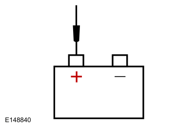
|

|
|
-
Measure:
Click to display connectors
|
Positive Lead
|
Measurement / Action
|
Negative Lead
|
|
C102C-1
|

|
Ground
|
Is the voltage within 0.5 volt of the recorded battery voltage?
| No |
TIGHTEN or INSTALL a new generator B+ nut as needed. For 1.5L EcoBoost,
REFER to: Generator - 1.5L EcoBoost (118kW/160PS) – I4 (414-02 Generator and Regulator, Removal and Installation).
For 2.0L EcoBoost, REFER to: Generator - 2.0L EcoBoost (184kW/250PS) – MI4 (414-02 Generator and Regulator, Removal and Installation).
For 2.5L Duratec, REFER to: Generator - 2.5L Duratec (125kW/170PS) (414-02 Generator and Regulator, Removal and Installation).
For 2.7L EcoBoost, REFER to: Generator - 2.7L EcoBoost (238kW/324PS) (414-02 Generator and Regulator, Removal and Installation).
VERIFY high current BJB
MEGA 8 fuse (275A) is OK. If OK, REPAIR the circuit. If not OK, REFER
to the Wiring Diagrams manual to identify the possible causes of the
circuit short.
|
|
| H3 CHECK THE VOLTAGE DROP IN THE GENERATOR B+ CIRCUIT |
-
With the engine running at idle, headlamps on and blower on high, measure:
Click to display connectors
|
Positive Lead
|
Measurement / Action
|
Negative Lead
|
|
C102C-1
|

|
|
-
Perform a wiggle test of the generator wiring and connections while measuring voltage drop.
Is the voltage drop less than 0.5 volt?
| No |
INSPECT and REPAIR any corrosion in the generator B+ circuit or positive battery cable connections.
|
|
| H4 "A" SENSE CIRCUIT LOAD TEST |
|
NOTICE:
The following step uses a test light to simulate
normal circuit loads. Use only the test light recommended in the Special
Tools table at the beginning of this section. To avoid connector
terminal damage, use the Flex Probe Kit for the test light probe
connection to the vehicle. Do not use the test light probe directly on
any connector.
NOTE:
This step puts a load on the "A" sense circuit. If
there are corroded or loose connections, loading the circuit may help
show the fault. A 250-350 mA incandescent 12-volt test lamp is required
for this step. This circuit cannot be loaded correctly using an
LED-style test lamp.
-
Disconnect Generator C1558A (2.0L EcoBoost or 2.5L Duratec) .
-
Disconnect Generator C102A (All other engines).
-
Measure and record:
|
Positive Lead
|
Measurement / Action
|
Negative Lead
|

|

|

|
-
For the 2.0L EcoBoost or 2.5L Duratec, install a test lamp between:
Click to display connectors
|
Positive Lead
|
Measurement / Action
|
Negative Lead
|
|
C1558A-3
|

|
Ground
|
-
For all other engines, install a test lamp between:
Click to display connectors
|
Positive Lead
|
Measurement / Action
|
Negative Lead
|
|
C102A-3
|

|
Ground
|
-
Perform a wiggle test on the generator wiring while measuring voltage.
-
For the 2.0L EcoBoost or 2.5L Duratec, perform a wiggle test on the generator wiring and measure:
Click to display connectors
|
Positive Lead
|
Measurement / Action
|
Negative Lead
|
|
C1558A-3
|

|
Ground
|
-
For all other engines, perform a wiggle test on the generator wiring and measure:
Click to display connectors
|
Positive Lead
|
Measurement / Action
|
Negative Lead
|
|
C102A-3
|

|
Ground
|
Is the "A" sense voltage within ±0.5 volt of the recorded battery voltage?
| No |
VERIFY high current BJB
fuse 55 (10A) is OK. If OK, REPAIR the circuit. If not OK, REFER to the
Wiring Diagrams manual to identify the possible causes of the circuit
short.
|
|
| H5 CHECK THE GENERATOR COMMAND CIRCUIT FOR A SHORT TO VOLTAGE |
-
Disconnect
PCM
C1915B (1.5L EcoBoost).
-
Disconnect
PCM
C1381B (2.0L EcoBoost).
-
Disconnect
PCM
C1551B (2.5L Duratec).
-
Disconnect
PCM
C1231B (2.7L EcoBoost).
-
For the 2.0L EcoBoost or 2.5L Duratec, perform a wiggle test on the generator wiring and measure:
Click to display connectors
|
Positive Lead
|
Measurement / Action
|
Negative Lead
|
|
C1558A-2
|

|
Ground
|
-
For all other engines, perform a wiggle test on the generator wiring and measure:
Click to display connectors
|
Positive Lead
|
Measurement / Action
|
Negative Lead
|
|
C102A-2
|

|
Ground
|
Is any voltage present?
|
| H6 CHECK THE GENERATOR COMMAND CIRCUIT FOR A SHORT TO GROUND |
-
For the 2.0L EcoBoost or 2.5L Duratec, perform a wiggle test on the generator wiring and measure:
Click to display connectors
|
Positive Lead
|
Measurement / Action
|
Negative Lead
|
|
C1558A-2
|

|
Ground
|
-
For all other engines, perform a wiggle test on the generator wiring and measure:
Click to display connectors
|
Positive Lead
|
Measurement / Action
|
Negative Lead
|
|
C102A-2
|

|
Ground
|
Is the resistance greater than 10,000 ohms?
|
| H7 CHECK THE GENERATOR COMMAND CIRCUIT FOR AN OPEN |
-
For the 1.5L EcoBoost, perform a wiggle test on the generator wiring and measure:
Click to display connectors
|
Positive Lead
|
Measurement / Action
|
Negative Lead
|
|
C1915B-59
|

|
C102A-2
|
-
For the 2.0L EcoBoost, perform a wiggle test on the generator wiring and measure:
Click to display connectors
|
Positive Lead
|
Measurement / Action
|
Negative Lead
|
|
C1381B-59
|

|
C1558A-2
|
-
For the 2.5L Duratec, perform a wiggle test on the generator wiring and measure:
Click to display connectors
|
Positive Lead
|
Measurement / Action
|
Negative Lead
|
|
C1551B-64
|

|
C1558A-2
|
-
For the 2.7L EcoBoost, perform a wiggle test on the generator wiring and measure:
Click to display connectors
|
Positive Lead
|
Measurement / Action
|
Negative Lead
|
|
C1231B-59
|

|
C102A-2
|
Is the resistance less than 3 ohms?
|
| H8 COMPARE THE GENERATOR MONITOR (GENMON) AND GENERATOR COMMAND (GENCMD) PIDS |
-
Connect
BJB fuse 7 (20A).
-
Connect
PCM
C1915B (1.5L EcoBoost).
-
Connect
PCM
C1381B (2.0L EcoBoost).
-
Connect
PCM
C1551B (2.5L Duratec).
-
Connect
PCM
C1231B (2.7L EcoBoost).
-
For the 2.0L EcoBoost or 2.5L Duratec, connect a fused jumper wire:
Click to display connectors
|
Positive Lead
|
Measurement / Action
|
Negative Lead
|
|
C1558A-1
|

|
C1558A-2
|
-
For all other engines, connect a fused jumper wire:
Click to display connectors
|
Positive Lead
|
Measurement / Action
|
Negative Lead
|
|
C102A-1
|

|
C102A-2
|
-
Using a diagnostic scan tool, view PCM Parameter Identifications (PIDs).
-
Monitor the PCM Parameter Identifications (PIDs) GENMON and GENCMD.
-
Perform a wiggle test of the generator wiring and connections.
Do the Parameter Identifications (PIDs) read within 5% of each other?
| Yes |
REMOVE the fused jumper wire. GO to H10
|
| No |
REMOVE the fused jumper wire. GO to H9
|
|
| H9 CHECK FOR CORRECT PCM (POWERTRAIN CONTROL MODULE)
OPERATION |
-
Disconnect and inspect all PCM connectors.
-
Repair:
-
corrosion (install new connector or terminals – clean module pins)
-
damaged or bent pins – install new terminals/pins
-
pushed-out pins – install new pins as necessary
-
Reconnect the PCM connectors. Make sure they seat and latch correctly.
-
Operate the system and determine if the concern is still present.
Is the concern still present?
| Yes |
CHECK OASIS for any applicable Technical Service Bulletins (TSBs). If a TSB exists for this concern, DISCONTINUE this test and FOLLOW the TSB
instructions. If no Technical Service Bulletins (TSBs) address this
concern,
 Click here to access Guided Routine (PCM).
 Internet Explorer version 11 or greater is required to perform this Pinpoint Test. Internet Explorer version 11 or greater is required to perform this Pinpoint Test.
CLEAR all Diagnostic Trouble Codes (DTCs) in all modules.
|
| No |
The system is operating correctly at this time. The
concern may have been caused by module connections. ADDRESS the root
cause of any connector or pin issues.
|
|
| H10 CHECK GENERATOR CLUTCH OPERATION |
-
Perform the generator clutch component test. GO to Pinpoint Test K
Is the generator clutch OK?
| Yes |
INSTALL a new generator. For 1.5L EcoBoost,
REFER to: Generator - 1.5L EcoBoost (118kW/160PS) – I4 (414-02 Generator and Regulator, Removal and Installation).
For 2.0L EcoBoost, REFER to: Generator - 2.0L EcoBoost (184kW/250PS) – MI4 (414-02 Generator and Regulator, Removal and Installation).
For 2.5L Duratec, REFER to: Generator - 2.5L Duratec (125kW/170PS) (414-02 Generator and Regulator, Removal and Installation).
For 2.7L EcoBoost, REFER to: Generator - 2.7L EcoBoost (238kW/324PS) (414-02 Generator and Regulator, Removal and Installation).
|
| No |
INSTALL a new generator clutch.
REFER to: Generator Pulley (414-02 Generator and Regulator, Removal and Installation).
|
|
DTC P0625 or P0626
Refer to Wiring Diagrams Cell 12 for schematic and connector information.
Normal Operation and Fault Conditions
The PCM monitors the generator output via the generator monitor (GENMON) circuit (generator field terminal circuit). If the PCM
cannot read the GENMON circuit due to an open or short to ground, when
the engine speed is greater than 2,000 rpm, the generator defaults to a
steady voltage of 13.5 volts and the PCM sends a request to the IPC
to illuminate the charging system warning indicator. A GENMON duty
cycle of 3% or less indicates a short to ground fault is present and
results in DTC P0625 setting in the PCM . A GENMON duty cycle of 98% or more indicates an open or short to voltage fault is present and results in DTC P0626 setting in the PCM.
Diagnostic Trouble Code (DTC) Fault Trigger Conditions
|
DTC
|
Description
|
Fault Trigger Conditions
|
|
P0625
|
Generator Field Terminal Circuit Low
|
The PCM sets this DTC if the GENMON circuit is shorted to ground, the "A" sense circuit is open or the B+ circuit is open. This DTC also sets by a faulted PCM or generator.
|
|
P0626
|
Generator Field Terminal Circuit High
|
The PCM sets this DTC if the GENMON circuit is open or shorted to power. This DTC can also be set by a faulted PCM or generator.
|
Possible Sources
-
Battery
-
Fuses or Fusible Links
-
Generator
-
Generator clutch.
-
PCM
-
Wiring, terminals or connectors
Visual Inspection and Diagnostic Pre-checks
-
Abnormal ignition-off current drain(s)
-
Inspect the high current BJB for loose or corroded connections.
-
Inspect the generator clutch.
PINPOINT TEST I : DTC P0625 OR P0626
| I1 PERFORM INSPECTION AND VERIFICATION |
-
Perform Inspection and Verification procedure in this section.
Was an obvious cause for an observed or reported concern found?
| Yes |
CORRECT the cause as necessary.
|
| No |
CHARGE or INSTALL a new battery as necessary.
REFER to: Battery (414-01 Battery, Mounting and Cables, Removal and Installation).
|
|
| I2 CHECK THE GENERATOR CONNECTIONS |
-
Disconnect all of the generator connectors and inspect for:
-
corrosion (install new connector or terminals – clean module pins)
-
damaged or bent pins – install new terminals/pins
-
pushed-out pins – install new pins as necessary
-
Reconnect the generator connectors. Make sure they seat and latch correctly.
-
Measure and record:
|
Positive Lead
|
Measurement / Action
|
Negative Lead
|

|

|

|
-
Measure:
Click to display connectors
|
Positive Lead
|
Measurement / Action
|
Negative Lead
|
|
C102C-1
|

|
Ground
|
Is the voltage within 0.5 volt of the recorded battery voltage?
| No |
TIGHTEN or INSTALL a new generator B+ nut as needed. For 1.5L EcoBoost,
REFER to: Generator - 1.5L EcoBoost (118kW/160PS) – I4 (414-02 Generator and Regulator, Removal and Installation).
For 2.0L EcoBoost, REFER to: Generator - 2.0L EcoBoost (184kW/250PS) – MI4 (414-02 Generator and Regulator, Removal and Installation).
For 2.5L Duratec, REFER to: Generator - 2.5L Duratec (125kW/170PS) (414-02 Generator and Regulator, Removal and Installation).
For 2.7L EcoBoost, REFER to: Generator - 2.7L EcoBoost (238kW/324PS) (414-02 Generator and Regulator, Removal and Installation).
VERIFY high current BJB
MEGA 8 fuse (275A) is OK. If OK, REPAIR the circuit. If not OK, REFER
to the Wiring Diagrams manual to identify the possible causes of the
circuit short.
|
|
| I3 CHECK THE VOLTAGE DROP IN THE GENERATOR B+ CIRCUIT |
-
With the engine running at idle, headlamps on and blower on high, measure:
Click to display connectors
|
Positive Lead
|
Measurement / Action
|
Negative Lead
|
|
C102C-1
|

|
|
-
Perform a wiggle test of the generator wiring and connections while measuring voltage drop.
Is the voltage drop less than 0.5 volt?
| Yes |
For DTC P0625, GO to I4
For DTC P0626, GO to I5
|
| No |
INSPECT and REPAIR any corrosion in the generator B+ circuit or positive battery cable connections.
|
|
| I4 "A" SENSE CIRCUIT LOAD TEST |
|
NOTICE:
The following step uses a test light to simulate
normal circuit loads. Use only the test light recommended in the Special
Tools table at the beginning of this section. To avoid connector
terminal damage, use the Flex Probe Kit for the test light probe
connection to the vehicle. Do not use the test light probe directly on
any connector.
NOTE:
This step puts a load on the "A" sense circuit. If
there are corroded or loose connections, loading the circuit may help
show the fault. A 250-350 mA incandescent 12-volt test lamp is required
for this step. This circuit cannot be loaded correctly using an
LED-style test lamp.
-
Disconnect Generator C1558A (2.0L EcoBoost or 2.5L Duratec).
-
Disconnect Generator C102A (All other engines).
-
Measure and record:
|
Positive Lead
|
Measurement / Action
|
Negative Lead
|

|

|

|
-
For the 2.0L EcoBoost or 2.5L Duratec, install a test lamp between:
Click to display connectors
|
Positive Lead
|
Measurement / Action
|
Negative Lead
|
|
C1558A-3
|

|
Ground
|
-
For all other engines, install a test lamp between:
Click to display connectors
|
Positive Lead
|
Measurement / Action
|
Negative Lead
|
|
C102A-3
|

|
Ground
|
-
For the 2.0L EcoBoost or 2.5L Duratec, perform a wiggle test on the generator wiring and measure:
Click to display connectors
|
Positive Lead
|
Measurement / Action
|
Negative Lead
|
|
C1558A-3
|

|
Ground
|
-
For all other engines, perform a wiggle test on the generator wiring and measure:
Click to display connectors
|
Positive Lead
|
Measurement / Action
|
Negative Lead
|
|
C102A-3
|

|
Ground
|
Is the "A" sense voltage within ±0.5 volt of the recorded battery voltage?
| No |
VERIFY high current BJB
fuse 55 (10A) is OK. If OK, REPAIR the circuit. If not OK, REFER to the
Wiring Diagrams manual to identify the possible causes of the circuit
short.
|
|
| I5 CHECK THE GENERATOR MONITOR CIRCUIT FOR A SHORT TO VOLTAGE |
-
Disconnect
PCM
C1915B (1.5L EcoBoost).
-
Disconnect
PCM
C1381B (2.0L EcoBoost).
-
Disconnect
PCM
C1551B (2.5L Duratec).
-
Disconnect
PCM
C1231B (2.7L EcoBoost).
-
For the 2.0L EcoBoost or 2.5L Duratec, perform a wiggle test on the generator wiring and measure:
Click to display connectors
|
Positive Lead
|
Measurement / Action
|
Negative Lead
|
|
C1558A-1
|

|
Ground
|
-
For all other engines, perform a wiggle test on the generator wiring and measure:
Click to display connectors
|
Positive Lead
|
Measurement / Action
|
Negative Lead
|
|
C102A-1
|

|
Ground
|
Is any voltage present?
|
| I6 CHECK THE GENERATOR MONITOR CIRCUIT FOR A SHORT TO GROUND |
-
For the 2.0L EcoBoost or 2.5L Duratec, perform a wiggle test on the generator wiring and measure:
Click to display connectors
|
Positive Lead
|
Measurement / Action
|
Negative Lead
|
|
C1558A-1
|

|
Ground
|
-
For all other engines, perform a wiggle test on the generator wiring and measure:
Click to display connectors
|
Positive Lead
|
Measurement / Action
|
Negative Lead
|
|
C102A-1
|

|
Ground
|
Is the resistance greater than 10,000 ohms?
|
| I7 CHECK THE GENERATOR MONITOR CIRCUIT FOR AN OPEN |
-
For the 1.5L EcoBoost, perform a wiggle test on the generator wiring and measure:
Click to display connectors
|
Positive Lead
|
Measurement / Action
|
Negative Lead
|
|
C1915B-26
|

|
C102A-1
|
-
For the 2.0L EcoBoost, perform a wiggle test on the generator wiring and measure:
Click to display connectors
|
Positive Lead
|
Measurement / Action
|
Negative Lead
|
|
C1381B-26
|

|
C1558A-1
|
-
For the 2.5L Duratec, perform a wiggle test on the generator wiring and measure:
Click to display connectors
|
Positive Lead
|
Measurement / Action
|
Negative Lead
|
|
C1551B-26
|

|
C1558A-1
|
-
For the 2.7L EcoBoost, perform a wiggle test on the generator wiring and measure:
Click to display connectors
|
Positive Lead
|
Measurement / Action
|
Negative Lead
|
|
C1231B-26
|

|
C102A-1
|
Is the resistance less than 3 ohms?
|
| I8 CHECK THE GENERATOR B+ INTERNAL RESISTANCE |
-
NOTE:
Failure to disconnect the battery will result in false resistance readings.
Disconnect the battery.
REFER to: Battery Disconnect and Connect (414-01 Battery, Mounting and Cables, General Procedures).
-
Disconnect Generator C102C
.
-
Measure:
Click to display connectors
|
Positive Lead
|
Measurement / Action
|
Negative Lead
|
|
Generator B+ Terminal
|

|
Generator case
|
Is the resistance greater than 25K ohms?
|
| I9 CHECK THE RESISTANCE OF THE VOLTAGE REGULATOR INTERNAL CIRCUITS |
-
Measure:
Click to display connectors
|
Positive Lead
|
Measurement / Action
|
Negative Lead
|
|
Generator pin 1 (Component Side)
|

|
Generator case
|
|
Generator pin 2 (Component Side)
|

|
Generator case
|
|
Generator pin 3 (Component Side)
|

|
Generator case
|
Are the resistances greater than 10,000 ohms?
|
| I10 COMPARE THE GENMON AND THE GENCMD PIDS |
-
Connect
PCM
C1915B (1.5L EcoBoost).
-
Connect
PCM
C1381B (2.0L EcoBoost).
-
Connect
PCM
C1551B (2.5L Duratec).
-
Connect
PCM
C1231B (2.7L EcoBoost).
-
For the 2.0L EcoBoost or 2.5L Duratec, connect a fused jumper wire:
Click to display connectors
|
Positive Lead
|
Measurement / Action
|
Negative Lead
|
|
C1558A-1
|

|
C1558A-2
|
-
For all other engines, connect a fused jumper wire:
Click to display connectors
|
Positive Lead
|
Measurement / Action
|
Negative Lead
|
|
C102A-1
|

|
C102A-2
|
-
Using a diagnostic scan tool, view PCM Parameter Identifications (PIDs).
-
Using the active command, set the PID GENVDSD to 14 volts.
-
Monitor the PCM Parameter Identifications (PIDs) GENMON and GENCMD.
-
Perform a wiggle test of the generator wiring and connections.
Do the Parameter Identifications (PIDs) read within 5% of each other?
| Yes |
REMOVE the fused jumper wire. GO to I12
|
| No |
REMOVE the fused jumper wire. GO to I11
|
|
| I11 CHECK FOR CORRECT PCM (POWERTRAIN CONTROL MODULE)
OPERATION |
-
Disconnect and inspect all PCM connectors.
-
Repair:
-
corrosion (install new connector or terminals – clean module pins)
-
damaged or bent pins – install new terminals/pins
-
pushed-out pins – install new pins as necessary
-
Reconnect the PCM connectors. Make sure they seat and latch correctly.
-
Operate the system and determine if the concern is still present.
Is the concern still present?
| Yes |
CHECK OASIS for any applicable Technical Service Bulletins (TSBs). If a TSB exists for this concern, DISCONTINUE this test and FOLLOW the TSB
instructions. If no Technical Service Bulletins (TSBs) address this
concern,
 Click here to access Guided Routine (PCM).
 Internet Explorer version 11 or greater is required to perform this Pinpoint Test. Internet Explorer version 11 or greater is required to perform this Pinpoint Test.
CLEAR all Diagnostic Trouble Codes (DTCs) in all modules.
|
| No |
The system is operating correctly at this time. The
concern may have been caused by module connections. ADDRESS the root
cause of any connector or pin issues.
|
|
| I12 CHECK GENERATOR CLUTCH OPERATION |
-
Perform the generator clutch component test. GO to Pinpoint Test K
Is the generator clutch OK?
| Yes |
INSTALL a new generator. For 1.5L EcoBoost,
REFER to: Generator - 1.5L EcoBoost (118kW/160PS) – I4 (414-02 Generator and Regulator, Removal and Installation).
For 2.0L EcoBoost, REFER to: Generator - 2.0L EcoBoost (184kW/250PS) – MI4 (414-02 Generator and Regulator, Removal and Installation).
For 2.5L Duratec, REFER to: Generator - 2.5L Duratec (125kW/170PS) (414-02 Generator and Regulator, Removal and Installation).
For 2.7L EcoBoost, REFER to: Generator - 2.7L EcoBoost (238kW/324PS) (414-02 Generator and Regulator, Removal and Installation).
|
| No |
INSTALL a new generator clutch.
REFER to: Generator Pulley (414-02 Generator and Regulator, Removal and Installation).
|
|
Load Shed Message Displays in Message Center
Refer to Wiring Diagrams Cell 12 for schematic and connector information.
Normal Operation and Fault Conditions
When the engine is off and the key is in on or accessory mode, and the BCM determines the battery state of charge is below 50%, or 45 minutes have elapsed, a load shed message is sent over the CAN.
This message turns off the audio/navigation system to save the
remaining battery charge. Under this condition the a load shed message
will be displayed to notify the driver that battery protection actions
are active:
-
System Off to Save Battery Turn Ignition Off displays on the FCDIM (without touchscreen controls)
-
SYSTEM OFF TO SAVE BATTERY PLEASE TURN IGNITION OFF OR START ENGINE displays on the FDIM (with touchscreen controls)
-
Battery Saver - System Off displays on the FDIM (with Sync)
These messages displaying may be normal operation and not indicate a fault. Refer to the Owner Literature and
REFER to: Charging System - System Operation and Component Description (414-00 Charging System - General Information, Description and Operation).
Load shed messages displaying with the engine running or only on the FCDIM or the FDIM (with touchscreen controls) indicates the audio system has detected a fault.
Possible Sources
-
Normal operation
-
Audio system
-
Battery
-
BCM
-
Fuses or Fusible Links
-
Generator
-
Wiring, terminals or connectors
Visual Inspection and Diagnostic Pre-checks
-
Inspect the high current BJB for loose or corroded connections.
-
Inspect the battery for loose or corroded connections.
-
Inspect the generator for loose or corroded connections.
-
Inspect the BJB for loose or corroded connections.
-
Inspect the high current BJB for loose or corroded connections.
-
Inspect C146 for loose or corroded connections.
-
Inspect battery and engine grounds for loose or corroded connections.
PINPOINT TEST J : LOAD SHED MESSAGE DISPLAYS IN MESSAGE CENTER
| J1 PERFORM INSPECTION AND VERIFICATION |
-
Perform Inspection and Verification procedure in this section.
Was an obvious cause for an observed or reported concern found?
| Yes |
CORRECT the cause as necessary.
|
|
| J2 VERIFY THE CUSTOMER CONCERN |
-
Verify the customer concern by operating the charging system.
Did the customer indicate battery saver message only appeared in the centerstack with the engine running?
| Yes |
Without touch screen or Sony audio,
REFER to: Information and Entertainment System (415-00 Information and Entertainment System - General Information)
.
With touch screen, REFER to: Information and
Entertainment System (415-00 Information and Entertainment System -
General Information)
.
With Sony Audio, REFER to: Information and
Entertainment System (415-00 Information and Entertainment System -
General Information)
.
|
|
| J3 VERIFY THE NETWORK |
-
Using a diagnostic scan tool, perform the Network Test.
Did the APIM, BCM, and PCM pass the Network Test?
| No |
REFER to: Communications Network (418-00 Module Communications Network, Diagnosis and Testing).
|
|
| J4 PERFORM PCM (POWERTRAIN CONTROL MODULE)
SELF TEST |
-
Using a diagnostic scan tool, perform the PCM self-test.
Were any battery or charging system related Diagnostic Trouble Codes (DTCs) retrieved?
| Yes |
REFER to PCM DTC chart in this section.
|
|
| J5 RETRIEVE ALL CONTINUOUS MEMORY DIAGNOSTIC TROUBLE CODES (CMDTCS) |
-
Using a diagnostic scan tool, retrieve all Continuous Memory Diagnostic Trouble Codes (CMDTCs).
Were any battery or charging system related Diagnostic Trouble Codes (DTCs) retrieved?
| Yes |
For BCM Diagnostic Trouble Codes (DTCs) refer to BCM DTC chart in this section.
For APIM or ACM Diagnostic Trouble Codes (DTCs), Refer to the appropriate section in Group 415 for the procedure.
For other battery or charging system related Diagnostic Trouble Codes (DTCs),
REFER to: Diagnostic Trouble Code Charts (100-00 General Information, Diagnosis and Testing).
|
|
| J6 CHECK BCM (BODY CONTROL MODULE)
BAT_ST_CHRG PID (PARAMETER IDENTIFICATION)
|
-
Using a diagnostic scan tool, view the BCM Parameter Identifications (PIDs).
-
Monitor the BCM BAT_ST_CHRG PID.
Does the PID indicate 50% or more?
|
| J7 RELEARN BATTERY STATE OF CHARGE |
|
NOTE:
The battery state of charge is too low and needs to
be relearned. Refer to the Description and Operation in this section for
more information on battery state of charge.
-
Remove all accessories from the lighter, all power outlets and DC/AC inverter.
-
NOTE:
The key should not be left in the vehicle but
should be left in a secure location away from the vehicle such as a lock
box.
Allow vehicle to sit undisturbed for at least 6 hours.
-
Using a diagnostic scan tool, view the BCM Parameter Identifications (PIDs).
-
Monitor the BCM BAT_ST_CHRG PID.
Does the PID indicate 50% or more?
| Yes |
The concern may have been caused by too low of a
battery state of charge. REVIEW Energy Management operation with
customer and return vehicle to customer.
|
|
| J8 VERIFY INLINE CONNECTOR |
-
Inspect inline connector C146 for secure connection.
-
Disconnect Inline connector C146
.
-
Inspect for:
-
corrosion (install new connector or terminals – clean module pins)
-
damaged or bent pins – install new terminals/pins
-
pushed-out pins – install new pins as necessary
Were any concerns present?
| Yes |
CORRECT the cause as necessary.
|
|
| J9 CHECK FOR CORRECT BCM (BODY CONTROL MODULE)
OPERATION |
-
Disconnect and inspect all BCM connectors.
-
Repair:
-
corrosion (install new connector or terminals – clean module pins)
-
damaged or bent pins – install new terminals/pins
-
pushed-out pins – install new pins as necessary
-
Reconnect the BCM connectors. Make sure they seat and latch correctly.
-
Operate the system and determine if the concern is still present.
Is the concern still present?
| Yes |
CHECK OASIS for any applicable Technical Service Bulletins (TSBs). If a TSB exists for this concern, DISCONTINUE this test and FOLLOW the TSB
instructions. If no Technical Service Bulletins (TSBs) address this
concern,
 Click here to access Guided Routine (BCM).
 Internet Explorer version 11 or greater is required to perform this Pinpoint Test. Internet Explorer version 11 or greater is required to perform this Pinpoint Test.
CLEAR all Diagnostic Trouble Codes (DTCs) in all modules.
|
| No |
The system is operating correctly at this time. The
concern may have been caused by module connections. ADDRESS the root
cause of any connector or pin issues.
|
|
Generator Clutch Component Test
Refer to Wiring Diagrams Cell 12 for schematic and connector information.
Normal Operation and Fault Conditions
The generator clutch allows the generator rotor to continue to rotate when the engine or FEAD
system slows. The clutch should slip freely and smoothly in a clockwise
direction. It should not rotate freely in the counterclockwise
direction. A loose FEAD
belt or a weak or binding tensioner can cause the pulley to overheat.
REFER to: Charging System - System Operation and Component Description (414-00 Charging System - General Information, Description and Operation).
PINPOINT TEST K : GENERATOR CLUTCH COMPONENT TEST
| K1 INSPECT THE GENERATOR CLUTCH |
-
Remove the generator. For 1.5L EcoBoost,
REFER to: Generator - 1.5L EcoBoost (118kW/160PS) – I4 (414-02 Generator and Regulator, Removal and Installation).
For 2.0L EcoBoost, REFER to: Generator - 2.0L EcoBoost (184kW/250PS) – MI4 (414-02 Generator and Regulator, Removal and Installation).
For 2.5L Duratec, REFER to: Generator - 2.5L Duratec (125kW/170PS) (414-02 Generator and Regulator, Removal and Installation).
For 2.7L EcoBoost, REFER to: Generator - 2.7L EcoBoost (238kW/324PS) (414-02 Generator and Regulator, Removal and Installation).
-
Inspect the generator clutch for heat damage.
Is there evidence of heat damage?
| Yes |
INSTALL a new generator clutch.
REFER to: Generator Pulley (414-02 Generator and Regulator, Removal and Installation).
INSPECT the FEAD system. For 1.5L EcoBoost,
REFER to: Accessory Drive (303-05A Accessory Drive - 1.5L EcoBoost (118kW/160PS) – I4, Diagnosis and Testing).
For 2.0L EcoBoost, REFER to: Accessory Drive (303-05B Accessory Drive - 2.0L EcoBoost (184kW/250PS) – MI4, Diagnosis and Testing).
For 2.5L Duratec, REFER to: Accessory Drive (303-05C Accessory Drive - 2.5L Duratec (125kW/170PS), Diagnosis and Testing).
For 2.7L EcoBoost, REFER to: Accessory Drive (303-05D Accessory Drive - 2.7L EcoBoost (238kW/324PS), Diagnosis and Testing).
|
|
| K2 CHECK THE GENERATOR CLUTCH FOR SMOOTH ROTATION |
-
Using a small screwdriver or similar tool, insert
the tool through the rubber button on the center of the pulley cap and
pry off the cap. Discard the cap. A new cap must be installed.
-
Using a 17 mm hex tool bit (such as a Snap-on®
SAM17E2 or equivalent) and socket wrench, insert the 17 mm hex tool bit
into the end of the clutch shaft.
-
While holding the clutch pulley firmly by hand, turn
the clutch shaft clockwise. The clutch shaft should rotate smoothly and
freely.
Does the clutch shaft rotation feel rough or seized?
| Yes |
INSTALL a new generator clutch.
REFER to: Generator Pulley (414-02 Generator and Regulator, Removal and Installation).
|
|
| K3 CHECK FOR REVERSE ROTATION RESISTANCE |
-
While holding the clutch pulley firmly by hand, turn the clutch shaft counterclockwise.
Is there some resistance (a spring feel)?
| No |
INSTALL a new generator clutch.
REFER to: Generator Pulley (414-02 Generator and Regulator, Removal and Installation).
|
|
| K4 CHECK FOR REVERSE ROTATION |
-
While holding the clutch pulley firmly by hand, turn the clutch shaft counterclockwise.
Does the clutch shaft rotate freely?
| Yes |
INSTALL a new generator clutch.
REFER to: Generator Pulley (414-02 Generator and Regulator, Removal and Installation).
|
| No |
INSTALL a new generator. For 1.5L EcoBoost,
REFER to: Generator - 1.5L EcoBoost (118kW/160PS) – I4 (414-02 Generator and Regulator, Removal and Installation).
For 2.0L EcoBoost, REFER to: Generator - 2.0L EcoBoost (184kW/250PS) – MI4 (414-02 Generator and Regulator, Removal and Installation).
For 2.5L Duratec, REFER to: Generator - 2.5L Duratec (125kW/170PS) (414-02 Generator and Regulator, Removal and Installation).
For 2.7L EcoBoost, REFER to: Generator - 2.7L EcoBoost (238kW/324PS) (414-02 Generator and Regulator, Removal and Installation).
|
|
System Operation
System Diagram
Network Message Chart
Module Network Input Messages — Body Control Module (BCM)
Broadcast Message
Originating Module
Message Purpose
Alternator fault
PCM
The PCM has detected a fault in the generator or generator circuits...
Other information:
Removal
Remove the rear bumper cover.
Refer to: Rear Bumper Cover (501-19 Bumpers, Removal and Installation).
Disconnect the electrical connector.
Release the tabs.
Remove the active park assist sensor.
Installation
To install, reverse the removal procedure.
Carry out the azimuth system check.
Refer..
Removal
WARNING:
Front seat backrest trim covers installed on seats equipped
with seat side airbags cannot be repaired. A new trim cover must be
installed. Cleaning is permissible. Failure to follow these instructions
may result in the seat side airbag deploying incorrectly and increase
the risk of serious personal injury or death in a crash.
NOTE:
LH seat shown, RH seat sim..
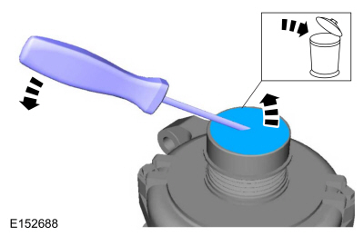
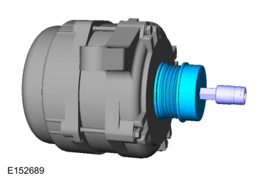
 Charging System - System Operation and Component Description. Description and Operation