Ford Fusion: Horn / Horn - System Operation and Component Description. Description and Operation
Ford Fusion 2013–2020 Service Manual / Electrical / Instrumentation and Warning Systems / Horn / Horn - System Operation and Component Description. Description and Operation
System Operation
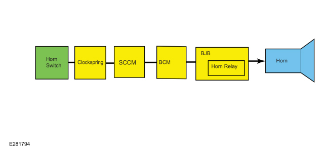
System Diagram
.jpg)
| Item | Description |
|---|---|
| 1 | BJB |
| 2 | Horn Relay |
| 3 | Horn Switch |
| 4 | Clockspring |
| 5 | SCCM |
| 6 | BCM |
| 7 | Horn |
Horn Operation
The horn switch consists of 2 sets of contacts separated by springs. The lower set is connected to ground and the upper set is connected to the horn signal circuit. When the driver airbag is pressed, it pushes down on the upper set of contacts, collapsing the springs and allowing the contacts to touch. When the contacts touch, it completes the circuit and provides the ground signal, which is routed through the clockspring to the SCCM and BCM. The BCM grounds the horn relay coil to energize the integrated relay in the BJB. When energized, the horn relay provides voltage to the horn, enabling the horn to sound.

 Horn. Diagnosis and Testing
DTC Chart
Diagnostics in this manual assume a certain skill level and knowledge of Ford-specific diagnostic practices. REFER to: Diagnostic Methods (100-00 General Information, Description and Operation)...
Other information:
Ford Fusion 2013–2020 Service Manual: Restraints Control Module (RCM). Removal and Installation
Removal NOTE: Removal steps in this procedure may contain installation details. When installing a new RCM, Programmable Module Installation (PMI) is required. Refer to the diagnostic scan tool instructions to carry out Programmable Module Installation (PMI)...
Ford Fusion 2013–2020 Service Manual: Specifications
General Specifications Item Specification 1.5L EcoBoost - 150A (base) Generator pulley ratio 2.42:1 Generator pulley replaceable Yes Generator pulley type Overrunning Alternator Decoupler (OAD) Rating 90 amps at 750 rpm (min) to 155 amps at 2,400 rpm (max) Voltage regulator type..
Categories
- Manuals Home
- 2nd Generation Ford Fusion Owners Manual
- 2nd Generation Ford Fusion Service Manual
- Cylinder Head. Removal and Installation
- Main Control Valve Body. Removal and Installation
- Front Controls Interface Module (FCIM). Removal and Installation
- New on site
- Most important about car
Power Door Locks
The power door lock control is on the driver and front passenger door panels.
Copyright © 2026 www.fofusion2.com