Ford Fusion: Power Transfer Unit - 6-Speed Automatic Transmission – 6F35 / Power Transfer Unit Rear Seal. Removal and Installation
Ford Fusion 2013–2020 Service Manual / Powertrain / Four-Wheel Drive Systems / Power Transfer Unit - 6-Speed Automatic Transmission – 6F35 / Power Transfer Unit Rear Seal. Removal and Installation
Special Tool(s) / General Equipment
 |
205-126
(T78P-4851-A)
Holding Fixture, Drive Pinion Flange |
 |
308-877 Installer, Pinion Output Seal TKIT-2012A-FL TKIT-2012A-ROW |
| Puller | |
Removal
-
Remove the PTU/transfer case.
Refer to: Power Transfer Unit (308-07B Power Transfer Unit - 6-Speed Automatic Transmission – 6F35, Removal).
-
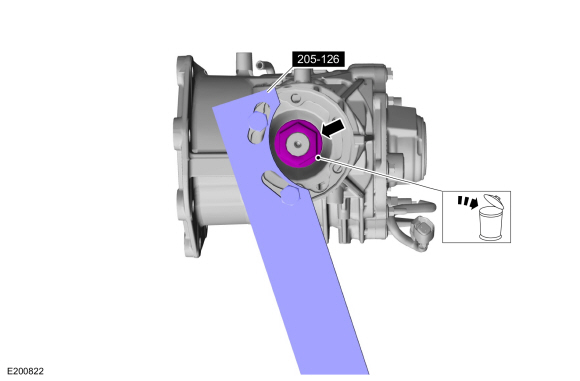
Using the special tool, remove and discard the pinion flange nut.
Use Special Service Tool: 205-126 (T78P-4851-A) Holding Fixture, Drive Pinion Flange.
 |
-
-
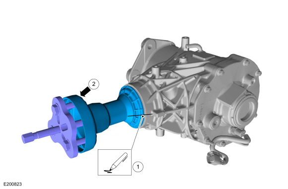
Mark the pinion flange and the transfer case for reassembly.
-
Using the puller, remove the pinion flange.
Use the General Equipment: Puller
-
Mark the pinion flange and the transfer case for reassembly.
 |
-
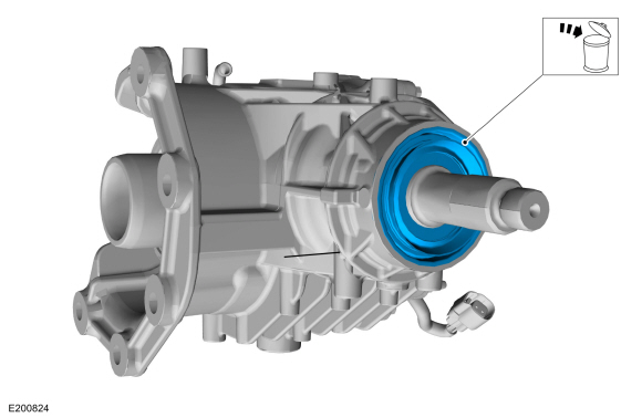
Remove and discard the transfer case rear seal.
 |
Installation
-
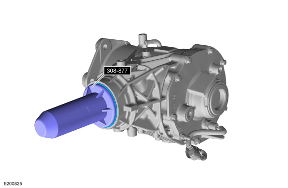
Using the special tool, install a new rear seal.
Use Special Service Tool: 308-877 Installer, Pinion Output Seal.
 |
-
Align the marks, install the pinion flange.
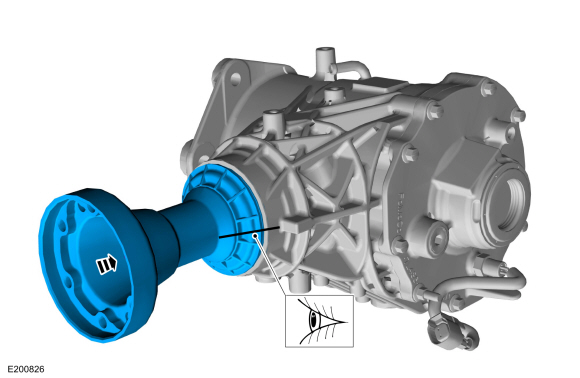 |
-
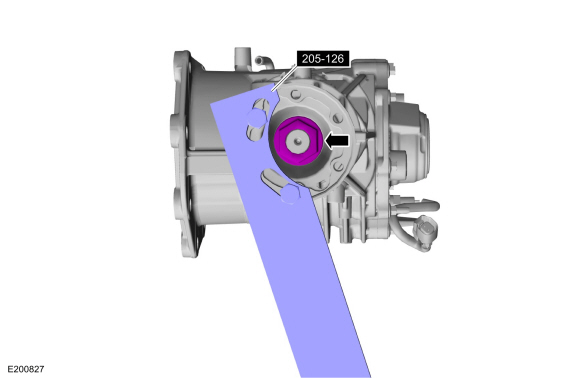
Using the special tool, install a new pinion flange nut.
Use Special Service Tool: 205-126 (T78P-4851-A) Holding Fixture, Drive Pinion Flange.
Torque: 173 lb.ft (235 Nm)
 |
-
Install the PTU/transfer case.
Refer to: Power Transfer Unit (308-07B Power Transfer Unit - 6-Speed Automatic Transmission – 6F35, Installation).
 Power Transfer Unit Input Shaft Seal. Removal and Installation
Special Tool(s) /
General Equipment
205-153
(T80T-4000-W)
Handle
308-875Installer, Inboard Cover SealTKIT-2012A-FLTKIT-2012A-ROW
308-878Installer, Input SealTKIT-2012A-FLTKIT-2012A-ROW
Removal
Remove the PTU/transfer case...
 Power Transfer Unit Vent. Removal and Installation
Removal
With the vehicle in NUETRAL, position it on a hoist.
Refer to: Jacking and Lifting - Overview (100-02 Jacking and Lifting, Description and Operation)...
Other information:
Ford Fusion 2013–2020 Service Manual: Transmission Fluid Heater Coolant Control Valve. Removal and Installation
Special Tool(s) / General Equipment Hose Clamp(s) Hose Clamp Remover/Installer Removal Remove the battery tray. Refer to: Battery Tray (414-01 Battery, Mounting and Cables, Removal and Installation). Remove the retainers and the battery tray bracket...
Ford Fusion 2013–2020 Service Manual: In-Vehicle Temperature and Humidity Sensor. Removal and Installation
Removal NOTE: Removal steps in this procedure may contain installation details. WARNING: Before beginning any service procedure in this section, refer to Safety Warnings in section 100-00 General Information. Failure to follow this instruction may result in serious personal injury...
Categories
- Manuals Home
- 2nd Generation Ford Fusion Owners Manual
- 2nd Generation Ford Fusion Service Manual
- Transmission - 1.5L EcoBoost (118kW/160PS) – I4. Removal and Installation
- Electrical
- Starter Motor. Removal and Installation
- New on site
- Most important about car
Manual Climate Control
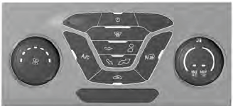
Note: Depending on your vehicle option package, the controls may look different from what you see here.
Copyright © 2026 www.fofusion2.com
