Ford Fusion: Electrical / Instrumentation and Warning Systems
Ford Fusion 2013–2020 Service Manual / Electrical / Instrumentation and Warning Systems
- Instrument Panel and Interior Switches Illumination
- Instrumentation, Message Center and Warning Chimes
- Horn
- Parking Aid
- Parking Aid - Vehicles With: Active Park Assist
 Thermostatic Expansion Valve. Removal and Installation
Removal
NOTICE:
During the removal or installation of components, cap, tape
or otherwise appropriately protect all openings and tubes/fittings to
prevent the ingress of dirt or other contamination...

Other information:
Ford Fusion 2013–2020 Owners Manual: Special Notices
New Vehicle Limited Warranty Vehicles sold in the United States and Canada For a detailed description of what is covered by your New Vehicle Limited Warranty, see your warranty guide that is available online. For more information, refer to our website and download your copy of the warranty guide. Vehicles sold outside the United States and Canada For a detailed description of what is covered..
Ford Fusion 2013–2020 Service Manual: Exhaust System - Overview. Description and Operation
Overview NOTICE: Do not use leaded fuel in a vehicle equipped with a catalytic converter. In a vehicle that is continually misfueled, the lead in the fuel will be deposited in the catalytic converter and completely blanket the catalyst. Lead reacts with platinum to "poison" the catalyst. Continuous use of leaded fuel can destroy the catalyst and render the catalytic converter useless. T..
Categories
- Manuals Home
- 2nd Generation Ford Fusion Owners Manual
- 2nd Generation Ford Fusion Service Manual
- Pre-Collision Assist (IF EQUIPPED)
- Electronic Parking Brake (EPB) Service Mode Activation and Deactivation. General Procedures
- Under Hood Overview - 1.5L EcoBoost™, 2.0L EcoBoost™, 2.5L, 2.7L EcoBoost™
- New on site
- Most important about car
Fuel Quality
Choosing the Right Fuel
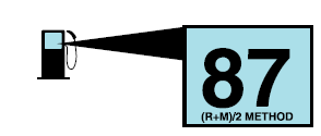
Your vehicle is designed to operate on regular unleaded gasoline with a minimum pump (R+M)/2 octane rating of 87.
Copyright © 2026 www.fofusion2.com