Ford Fusion: Climate Control System - General Information / Thermostatic Expansion Valve. Removal and Installation
Removal
NOTICE: During the removal or installation of components, cap, tape or otherwise appropriately protect all openings and tubes/fittings to prevent the ingress of dirt or other contamination. Remove caps, tape and other protective materials prior to installation.
NOTE: Removal steps in this procedure may contain installation details.
-
Refer to: Climate Control System Health and Safety Precautions (100-00 General Information, Description and Operation). WARNING:
Before beginning any service procedure in this
section, refer to Safety Warnings in section 100-00 General Information.
Failure to follow this instruction may result in serious personal
injury.
WARNING:
Before beginning any service procedure in this
section, refer to Safety Warnings in section 100-00 General Information.
Failure to follow this instruction may result in serious personal
injury.
-
Recover the refrigerant. Refer to the appropriate Recovery procedure in Group 412.
-
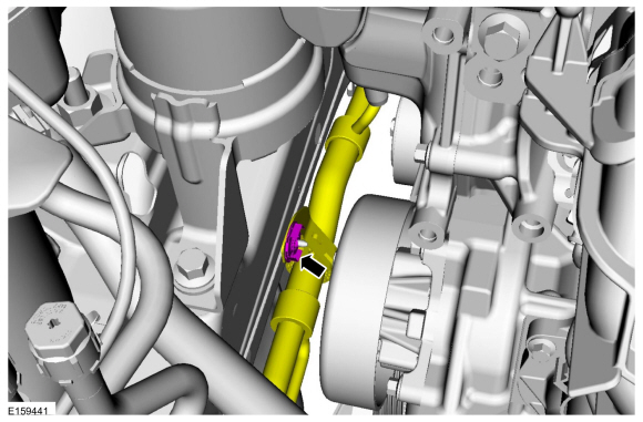
Remove the evaporator inlet and outlet manifold bracket nut.
Torque: 18 lb.in (2 Nm)
 |
-
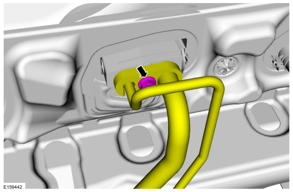
NOTICE: Make sure that all openings are sealed.
Remove the evaporator inlet and outlet manifold nut, disconnect the fitting. Discard the gasket seals.
-
Make sure to cover any open ports to prevent debris from entering the system.
Torque: 133 lb.in (15 Nm)
-
Make sure to cover any open ports to prevent debris from entering the system.
 |
-
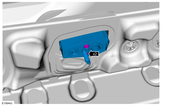
NOTICE: Make sure that all openings are sealed.
Remove the bolts and the thermostatic expansion valve. Discard the gasket seals.
-
Make sure to cover any open ports to prevent debris from entering the system.
Torque: 71 lb.in (8 Nm)
-
Make sure to cover any open ports to prevent debris from entering the system.
 |
Installation
-
To install, reverse the removal procedure.
-
NOTICE: Only use the specified material to lubricate the seals.
Install and lubricate new O-ring seals. Refer to the appropriate Specifications in Group 412.
-
Lubricate the refrigerant system with the correct amount
of clean PAG oil. Refer to the appropriate Refrigerant Oil Adding
procedure in Group 412.
 Sunload Sensor. Removal and Installation
Removal
NOTE:
Removal steps in this procedure may contain installation details.
WARNING:
Before beginning any service procedure in this
section, refer to Safety Warnings in section 100-00 General Information...

Other information:
Ford Fusion 2013–2020 Owners Manual: Pre-Collision Assist (IF EQUIPPED)
WARNING: You are responsible for controlling your vehicle at all times. The system is designed to be an aid and does not relieve you of your responsibility to drive with due care and attention. Failure to follow this instruction could result in the loss of control of your vehicle, personal injury or death. WARNING: The system does not detect vehicles that are driving in a different direct..
Ford Fusion 2013–2020 Service Manual: In-Vehicle Temperature and Humidity Sensor. Removal and Installation
Removal NOTE: Removal steps in this procedure may contain installation details. WARNING: Before beginning any service procedure in this section, refer to Safety Warnings in section 100-00 General Information. Failure to follow this instruction may result in serious personal injury. Refer to: Climate Control System Health and Safety Precautions (100-00 General Informat..
Categories
- Manuals Home
- 2nd Generation Ford Fusion Owners Manual
- 2nd Generation Ford Fusion Service Manual
- Memory Function
- Engine
- Pre-Collision Assist (IF EQUIPPED)
- New on site
- Most important about car
Using Seatbelts During Pregnancy
WARNING: Always ride and drive with your seatback upright and properly fasten your seatbelt. Fit the lap portion of the seatbelt snugly and low across the hips. Position the shoulder portion of the seatbelt across your chest. Pregnant women must follow this practice. See the following figure.
