Ford Fusion: Information and Entertainment System - General Information - Vehicles With: SYNC 3 / Audio Unit Antenna Cable. Removal and Installation
Removal
NOTE: The original equipment body antenna cable is part of the wiring harness and cannot be removed. This procedure refers to replacement of the body antenna cable by overlaying existing body harness with a new body cable and securing it to the wiring harness.
NOTE: The Satellite radio cable(s) in-line connection is located under the floor console.
Body antenna cable access-all vehicles
-
Remove the following items:
-
Remove both front seats.
Refer to: Front Seat (501-10A Front Seats, Removal and Installation).
-
Remove both B-pillar trim panels.
Refer to: B-Pillar Trim Panel (501-05 Interior Trim and Ornamentation, Removal and Installation).
-
Remove both upper C-pillar trim panels.
Refer to: C-Pillar Upper Trim Panel (501-05 Interior Trim and Ornamentation, Removal and Installation).
-
Remove both C-pillar lower trim panels.
Refer to: C-Pillar Lower Trim Panel (501-05 Interior Trim and Ornamentation, Removal and Installation).
-
Remove the floor console.
Refer to: Floor Console (501-12 Instrument Panel and Console, Removal and Installation).
-
Remove both rear seat backrests.
Refer to: Rear Seat Backrest (501-10B Rear Seats, Removal and Installation).
-
Remove both D-pillar trim panels.
Refer to: D-Pillar Trim Panel (501-05 Interior Trim and Ornamentation, Removal and Installation).
-
Carefully lower the rear of the headliner.
Refer to: Headliner (501-05 Interior Trim and Ornamentation, Removal and Installation).
-
Remove both front seats.
Body antenna cable access-vehicles equipped with a
-
Vehicles equipped with a TCU.
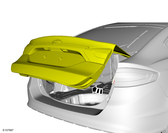
Open the luggage compartment lid.
 |
-
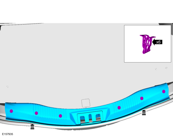
Release the clips and remove the rear plate.
 |
-
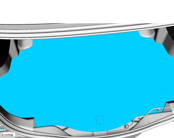
Remove the loadspace floor.
 |
-
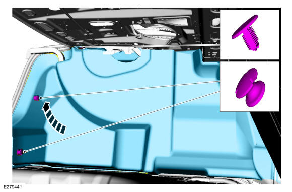
Remove the retainers and the LH loadspace trim panel.
 |
-
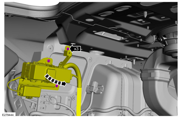
On hybrid or battery electric vehicles.
Remove the bolts and position the junction boy aside.
Torque: 44 lb.in (5 Nm)
 |
-
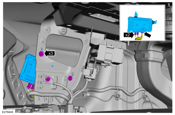
Remove the screws, disconnect the electrical connectors and remove the TCU.
Torque: 44 lb.in (5 Nm)
 |
Instrument panel antenna cable
-
Remove the following items:
-
Remove the floor console.
Refer to: Floor Console (501-12 Instrument Panel and Console, Removal and Installation).
-
Remove the ACM.
Refer to: Audio Front Control Module (ACM) (415-00 Information and Entertainment System - General Information - Vehicles With: SYNC 3, Removal and Installation).
-
Remove the floor console.
-
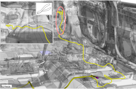
NOTE: Instrument panel antenna cable routing shown.
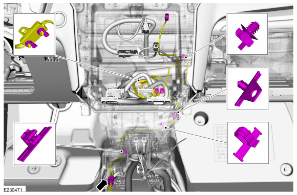
Disconnect the body antenna cable to instrument panel antenna cable in-line connector and remove the instrument panel antenna cable following the routing shown.
 |
Installation
Body antenna cable-Vehicles not equipped with
-
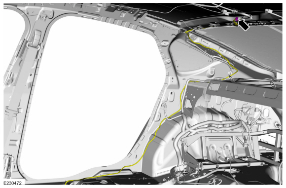
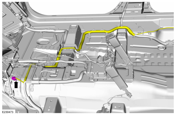
NOTE: D-pillar body antenna cable routing shown.
Cut the ends off the old body antenna cable. Overlay the new body antenna cable on the vehicle wiring harness following the routing shown. Secure the new antenna body cable to the wiring harness with tape or zip ties as necessary.
 |
-
NOTE: Floor body antenna cable routing shown.
Cut the ends off the old body antenna cable. Overlay the new body antenna cable on the vehicle wiring harness following the routing shown. Secure the new antenna body cable to the wiring harness with tape or zip ties as necessary.
 |
Body antenna cable-Vehicles equipped with
-
NOTE: D-pillar body antenna cable routing shown.
Cut the ends off the old body antenna cable. Overlay the new body antenna cable on the vehicle wiring harness following the routing shown. Secure the new antenna body cable to the wiring harness with tape or zip ties as necessary.
 |
-
NOTE: Floor body antenna cable routing shown.
Cut the ends off the old body antenna cable. Overlay the new body antenna cable on the vehicle wiring harness following the routing shown. Secure the new antenna body cable to the wiring harness with tape or zip ties as necessary.
 |
-
NOTE: TCUantenna cable routing shown.
Cut the end off the old body antenna cable. Overlay the new body antenna cable on the vehicle wiring harness following the routing shown. Secure the new antenna body cable to the wiring harness with tape or zip ties as necessary.
 |
Instrument panel antenna cable
-
NOTE: Instrument panel antenna cable routing shown.
Route the instrument panel antenna cable following the routing shown and connect the body antenna cable to instrument panel antenna cable in-line connector.
 |
 Audio Unit Antenna. Removal and Installation
Removal
NOTE:
Removal steps in this procedure may contain installation details.
Roof mounted antenna
Carefully lower the rear of the headliner...
 Front Control/Display Interface Module (FCDIM) - Police. Removal and Installation
Removal
NOTE:
Removal steps in this procedure may contain installation details.
NOTE:
If installing a new module, it is necessary to
upload the module configuration information to the scan tool prior to
removing the module...
Other information:
Ford Fusion 2013–2020 Service Manual: Transmission Description - System Operation and Component Description. Description and Operation
System Diagram Item Description 1 SSB 2 SSC 3 SSD 4 SSE 5 LPC Solenoid 6 TCC Solenoid 7 OSS Sensor 8 TSS Sensor 9 Transmission 10 Transmission 11 TR Sensor 12 TFT Sensor 13 SSA 14 PCM Network Message Chart Broadcast Message Originating Module Message Purpose Engine Speed ..
Ford Fusion 2013–2020 Owners Manual: Stowing the Flat Tire Using the Retainer Strap (If Equipped)
You can temporarily stow the full-size road wheel in the spare tire compartment. Find the flat tire retainer strap tucked inside the jack channel. Locate the jack bolt-down bracket. Push the retainer strap through the jack bolt-down bracket. Put the jack and lug wrench away. Make sure you fasten the jack so it does not rattle when you drive. Stow the flat tire on the floor in the cargo a..
Categories
- Manuals Home
- 2nd Generation Ford Fusion Owners Manual
- 2nd Generation Ford Fusion Service Manual
- Engine - 1.5L EcoBoost (118kW/160PS) – I4
- Automatic Transmission - 6-Speed Automatic Transmission – 6F35
- Electrical
- New on site
- Most important about car
Parallel Parking
The system detects available parallel parking spaces and steers your vehicle into the space. You control the accelerator, gearshift and brakes. The system visually and audibly guides you into a parallel parking space.
 Press the button once to search
for a parking space.
Press the button once to search
for a parking space.