Ford Fusion: Information and Entertainment System - General Information - Vehicles With: SYNC 3 / Audio Digital Signal Processing (DSP) Module. Removal and Installation
Removal
NOTE: Removal steps in this procedure may contain installation details.
-
Refer to: Health and Safety Precautions (100-00 General Information, Description and Operation). WARNING:
Before beginning any service procedure in this
section, refer to Safety Warnings in section 100-00 General Information.
Failure to follow this instruction may result in serious personal
injury.
WARNING:
Before beginning any service procedure in this
section, refer to Safety Warnings in section 100-00 General Information.
Failure to follow this instruction may result in serious personal
injury.
-
NOTE: If installing a new module, it is necessary to upload the module configuration information to the scan tool prior to removing the module. This information must be downloaded into the new module after installation.
Upload the audio DSP module configuration information to the scan tool by following the scan tool on-screen instructions.
-
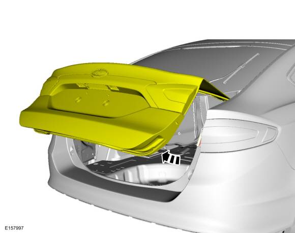
Open the luggage compartment lid.
 |
-
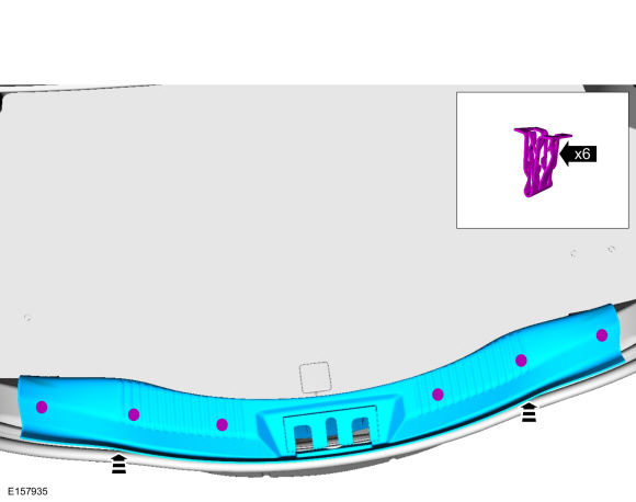
Release the clips and remove the rear plate.
 |
-
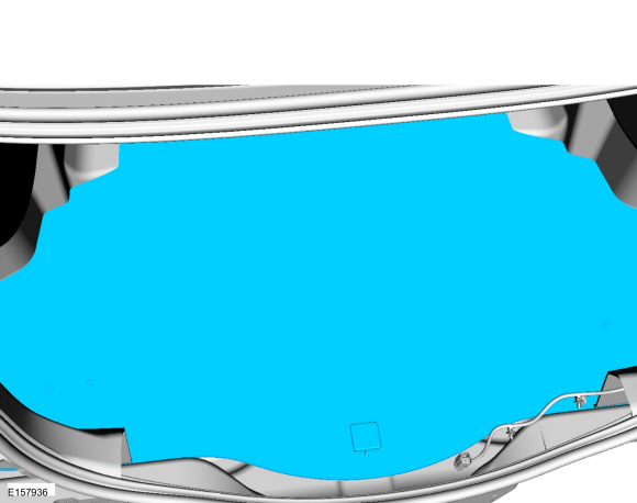
Remove the carpeting from the working area.
 |
-
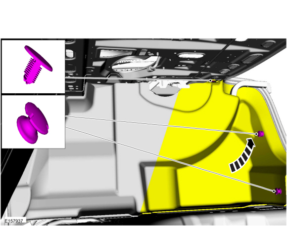
Remove the retainers and position aside the lid trim panel.
 |
-
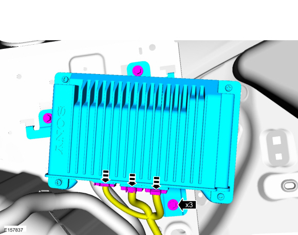
Remove the bolts and the DSP.
-
Disconnect the electrical connectors.
Torque: 62 lb.in (7 Nm)
-
Disconnect the electrical connectors.
 |
Installation
-
To install reverse the removal procedure.
-
Download the audio module configuration information from the scan tool to the new audio DSP following the scan tool on-screen instructions.
 Active Noise Control Microphone. Removal and Installation
Removal
NOTE:
Removal steps in this procedure may contain installation details.
WARNING:
Before beginning any service procedure in this
section, refer to Safety Warnings in section 100-00 General Information...
 Audio Front Control Module (ACM). Removal and Installation
Removal
NOTE:
Make sure that any media is ejected from unit.
NOTE:
Removal steps in this procedure may contain installation details.
WARNING:
Before beginning any service procedure in this
section, refer to Safety Warnings in section 100-00 General Information...
Other information:
Ford Fusion 2013–2020 Service Manual: Roof Panel - Vehicles With: Roof Opening Panel. Removal and Installation
Special Tool(s) / General Equipment Resistance Spotwelding Equipment Spherical Cutter Grinder Spot Weld Drill Bit Locking Pliers Materials Name Specification Metal Bonding AdhesiveTA-1, TA-1-B, 3M™ 08115, LORD Fusor® 108B - Seam SealerTA-2-B, 3M™ 08308, LORD Fusor® 803DTM - Removal NOTICE: Before beginning any servic..
Ford Fusion 2013–2020 Service Manual: Parking Aid - Component Location. Description and Operation
Component Location, Parking Aid - Audible Item Description 1 Front parking aid sensors 2 Parking aid switch (if equipped) 3 Rear speakers (part of audio system) 4 Rear parking aid sensors 5 Front speakers (part of audio system) 6 PAM (integral to the BCM Component Location, Parking Aid - Video Item Description 1 ..
Categories
- Manuals Home
- 2nd Generation Ford Fusion Owners Manual
- 2nd Generation Ford Fusion Service Manual
- Cylinder Head. Removal and Installation
- Main Control Valve Body. Removal and Installation
- Pre-Collision Assist (IF EQUIPPED)
- New on site
- Most important about car
Using Seatbelts During Pregnancy
WARNING: Always ride and drive with your seatback upright and properly fasten your seatbelt. Fit the lap portion of the seatbelt snugly and low across the hips. Position the shoulder portion of the seatbelt across your chest. Pregnant women must follow this practice. See the following figure.
