Ford Fusion: Engine Cooling - 1.5L EcoBoost (118kW/160PS) – I4 / Thermostat Housing. Removal and Installation
Ford Fusion 2013–2020 Service Manual / Powertrain / Engine / Engine Cooling - 1.5L EcoBoost (118kW/160PS) – I4 / Thermostat Housing. Removal and Installation
Special Tool(s) / General Equipment
| Hose Clamp Remover/Installer |
Removal
NOTE: Removal steps in this procedure may contain installation details.
-
Remove the A/C compressor.
Refer to: Air Conditioning (A/C) Compressor - 1.5L EcoBoost (118kW/160PS) – I4 (412-00 Climate Control System - General Information, Removal and Installation).
-
Drain the cooling system.
Refer to: Engine Cooling System Draining, Vacuum Filling and Bleeding (303-03A Engine Cooling - 1.5L EcoBoost (118kW/160PS) – I4, General Procedures).
-
-
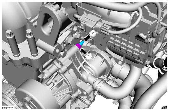
Remove the nut.
Torque: 159 lb.in (18 Nm)
-
NOTE: Double nut the stud and use a torque adaptor.
Remove the stud bolt.
Torque: 44 lb.in (5 Nm)
-
Remove the nut.
 |
-
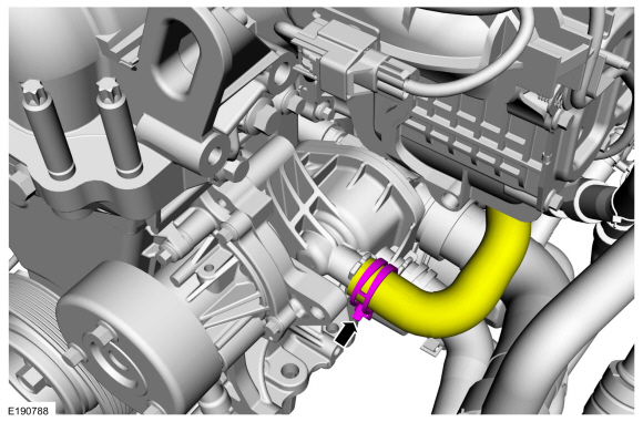
Release the clamp and disconnect the lower radiator hose.
Use the General Equipment: Hose Clamp Remover/Installer
 |
-
NOTE: Make sure that the mating faces are clean and free of foreign material.
NOTE: Install a new seal if the housing is going to be reinstalled.
-
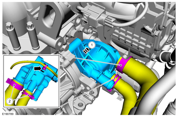
Remove the thermostat housing.
-
Release the clamps, disconnect the coolant hoses and detach the wiring harness retainer.
Use the General Equipment: Hose Clamp Remover/Installer
-
Remove the thermostat housing.
 |
Installation
-
To install, reverse the removal procedure.
 Transmission Fluid Heater Coolant Control Valve. Removal and Installation
Special Tool(s) /
General Equipment
Hose Clamp(s)
Hose Clamp Remover/Installer
Removal
Remove the battery tray.
Refer to: Battery Tray (414-01 Battery, Mounting and Cables, Removal and Installation)...

Other information:
Ford Fusion 2013–2020 Service Manual: Radiator Grille Opening Panel Reinforcement. Removal and Installation
Removal NOTE: Left hand (LH) side shown, right hand (RH) side similar. NOTE: Engine removed for clarity. Overview Remove the hood and prop rod. Refer to: Hood (501-02 Front End Body Panels, Removal and Installation). On Both Sides: Remove the fender and splash shield. On Both Sides: Remove the headlamp assembly. Refer to:..
Ford Fusion 2013–2020 Service Manual: Lower Arm. Removal and Installation
Special Tool(s) / General Equipment Vehicle/Axle Stands Removal NOTICE: Suspension fasteners are critical parts that affect the performance of vital components and systems. Failure of these fasteners may result in major service expense. Use the same or equivalent parts if replacement is necessary. Do not use a replacement part of lesser quality or substitute design. Tighten fast..
Categories
- Manuals Home
- 2nd Generation Ford Fusion Owners Manual
- 2nd Generation Ford Fusion Service Manual
- Front Controls Interface Module (FCIM). Removal and Installation
- Transmission - 1.5L EcoBoost (118kW/160PS) – I4. Removal and Installation
- Main Control Valve Body. Removal and Installation
- New on site
- Most important about car
Power Door Locks
The power door lock control is on the driver and front passenger door panels.
Copyright © 2026 www.fofusion2.com