Ford Fusion: Rear End Sheet Metal Repairs / Rear Side Member. Removal and Installation
Special Tool(s) / General Equipment
| Resistance Spotwelding Equipment | |
| 8 mm Drill Bit | |
| MIG/MAG Welding Equipment | |
| Spot Weld Drill Bit | |
| Locking Pliers |
Materials
| Name | Specification |
|---|---|
| Seam Sealer TA-2-B, 3M™ 08308, LORD Fusor® 803DTM |
- |
Removal
NOTICE: Battery electric vehicle (BEV), hybrid electric vehicle (HEV) and plug-in hybrid electric vehicle (PHEV) contain a high-voltage battery. Before cutting or welding near the high-voltage battery it must be removed to avoid damage.
NOTE: Rear doors removed for clarity.
NOTE: Left hand (LH) side shown, right hand (RH) side similar.
NOTE: Factory welds may be substituted with resistance or metal inert gas (MIG) plug welds. Resistance welds may not be placed directly over original location. They must be placed adjacent to original location and match factory welds in quantity. Metal inert gas (MIG) plug welds must equal factory welds in both location and quantity.
NOTE: Adequately protect all adjacent areas against cutting, grinding and welding procedures.
-
Depower the SRS.
Refer to: Supplemental Restraint System (SRS) Depowering and Repowering (501-20B) .
-
Remove the rocker panel moulding.
Refer to: Rocker Panel Moulding (501-08 Exterior Trim and Ornamentation, Removal and Installation).
-
Remove the rear seat.
Refer to: Rear Seat Cushion (501-10B Rear Seats, Removal and Installation).
Refer to: Rear Seat Backrest (501-10B) .
-
Remove the B, C and D-pillar trim panels.
Refer to: B-Pillar Trim Panel (501-05) .
Refer to: C-Pillar Upper Trim Panel (501-05) .
Refer to: C-Pillar Lower Trim Panel (501-05 Interior Trim and Ornamentation, Removal and Installation).
Refer to: D-Pillar Trim Panel (501-05) .
-
Remove the luggage compartment trim and spare tire.
-
Position the carpet and all wiring harnesses away from the working area.
-
Remove the rear bumper.
Refer to: Rear Bumper (501-19) .
-
If Required:
Dimensionally restore the vehicle to pre-damage condition.
Refer to: Body and Frame (501-26) .
-
Remove the muffler and tailpipe.
Refer to: Muffler and Tailpipe (309-00A Exhaust System - 1.5L EcoBoost (118kW/160PS) – I4, Removal and Installation).
Refer to: Muffler and Tailpipe (309-00D) .
Refer to: Muffler and Tailpipe (309-00G) .
Refer to: Muffler and Tailpipe (309-00J) .
-
Remove the upper arm, lower arm and spring.
Refer to: Upper Arm (204-02) .
Refer to: Lower Arm (204-02) .
Refer to: Spring (204-02 Rear Suspension, Removal and Installation).
-
Remove the rear floor panel reinforcement.
Refer to: Rear Floor Panel Reinforcement (501-30 Rear End Sheet Metal Repairs, Removal and Installation).
-
Remove the rear side member reinforcement panel.
Refer to: Rear Side Member Reinforcement Panel (501-30 Rear End Sheet Metal Repairs, Removal and Installation).
-
Remove the rear floor panel.
Refer to: Rear Floor Panel (501-30 Rear End Sheet Metal Repairs, Removal and Installation).
-
Remove the rear floor panel crossmember.
Refer to: Rear Floor Panel Crossmember (501-30 Rear End Sheet Metal Repairs, Removal and Installation).
-
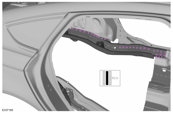
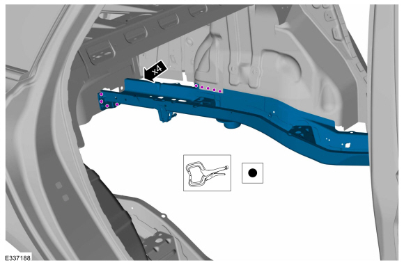
Remove the welds.
Use the General Equipment: Spot Weld Drill Bit
 |
-
NOTE: Pay particular attention to the location of adhesive and sealer to aid in installation.
Remove the welds and the side member.
 |
Installation
NOTICE: Battery electric vehicle (BEV), hybrid electric vehicle (HEV) and plug-in hybrid electric vehicle (PHEV) contain a high-voltage battery. Before cutting or welding near the high-voltage battery it must be removed to avoid damage.
NOTICE: The high-voltage battery in a battery electric vehicle (BEV), hybrid electric vehicle (HEV) or plug-in hybrid electric vehicle (PHEV) can be affected and damaged by excessively high temperatures. The temperature in some body shop paint booths can exceed 60° C (140° F). Therefore, during refinishing operations, the paint booth temperature must set at or below 60° C (140° F) with a bake time of 45 minutes or less. Temperatures in excess of 60° C (140° F) or bake durations longer than 45 minutes will require the high-voltage battery be removed from the vehicle prior to placing in the paint booth.
NOTICE: If refinishing cure temperatures exceed 60° C (140° F), the charge port light ring on plug-in vehicles must be removed.
NOTE: Rear doors removed for clarity.
NOTE: Left hand (LH) side shown, right hand (RH) side similar.
NOTE: Factory welds may be substituted with resistance or metal inert gas (MIG) plug welds. Resistance welds may not be placed directly over original location. They must be placed adjacent to original location and match factory welds in quantity. Metal inert gas (MIG) plug welds must equal factory welds in both location and quantity.
NOTE: Adequately protect all adjacent areas against cutting, grinding and welding procedures.
-
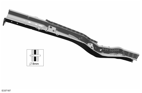
NOTE: The rear side member includes the bumper bracket.
Drill plug weld holes in the replacement side member.
Use the General Equipment: 8 mm Drill Bit
 |
-
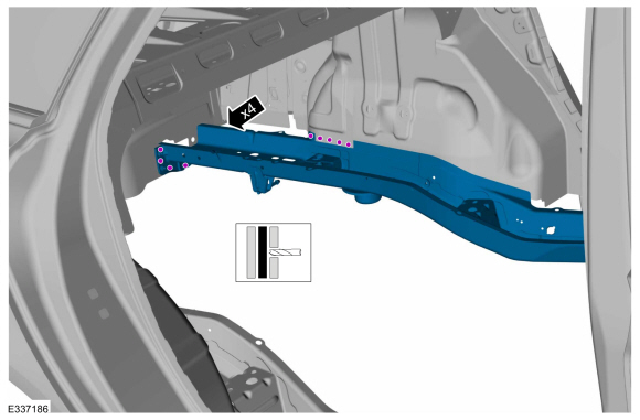
Install, properly position, clamp and welds the side member.
Use the General Equipment: Locking Pliers
Use the General Equipment: Resistance Spotwelding Equipment
 |
-
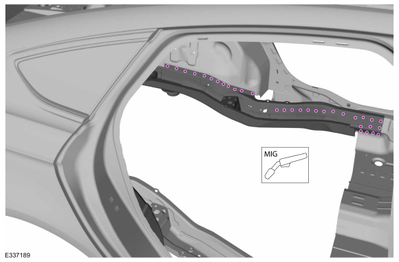
Install the welds.
Use the General Equipment: MIG/MAG Welding Equipment
 |
-
Dress all welds as necessary using typical metal finishing techniques.
-
Install the rear floor panel crossmember.
Refer to: Rear Floor Panel Crossmember (501-30 Rear End Sheet Metal Repairs, Removal and Installation).
-
Install the rear floor panel.
Refer to: Rear Floor Panel (501-30 Rear End Sheet Metal Repairs, Removal and Installation).
-
Install the rear side member reinforcement panel.
Refer to: Rear Side Member Reinforcement Panel (501-30 Rear End Sheet Metal Repairs, Removal and Installation).
-
Install the rear floor panel reinforcement.
Refer to: Rear Floor Panel Reinforcement (501-30 Rear End Sheet Metal Repairs, Removal and Installation).
-
Install the rear exhaust mounting bracket.
Refer to: Rear Exhaust Mounting Bracket (501-30 Rear End Sheet Metal Repairs, Removal and Installation).
-
Install the rear suspension bracket reinforcement.
Refer to: Rear Suspension Bracket Reinforcement (501-30 Rear End Sheet Metal Repairs, Removal and Installation).
-
Seam Sealing:
All seams must be sealed to production level.
Material: Seam Sealer / TA-2-B, 3M™ 08308, LORD Fusor® 803DTM
-
Refinish the entire repair using a Ford approved paint system.
-
Restore corrosion protection.
Refer to: Corrosion Prevention (501-25 Body Repairs - General Information, General Procedures).
-
Install the upper arm, lower arm and spring.
Refer to: Upper Arm (204-02) .
Refer to: Lower Arm (204-02) .
Refer to: Spring (204-02 Rear Suspension, Removal and Installation).
-
Install the muffler and tailpipe.
Refer to: Muffler and Tailpipe (309-00A Exhaust System - 1.5L EcoBoost (118kW/160PS) – I4, Removal and Installation).
Refer to: Muffler and Tailpipe (309-00D) .
Refer to: Muffler and Tailpipe (309-00G) .
Refer to: Muffler and Tailpipe (309-00J) .
-
Position all wiring harnesses and the carpet to original locations.
-
Install the luggage compartment trim and spare tire.
-
Install the rear seat.
Refer to: Rear Seat Backrest (501-10B) .
Refer to: Rear Seat Cushion (501-10B Rear Seats, Removal and Installation).
-
Install the B, C and D-pillar trim panels.
Refer to: D-Pillar Trim Panel (501-05) .
Refer to: C-Pillar Lower Trim Panel (501-05 Interior Trim and Ornamentation, Removal and Installation).
Refer to: C-Pillar Upper Trim Panel (501-05) .
Refer to: B-Pillar Trim Panel (501-05) .
-
Install the rear bumper.
Refer to: Rear Bumper (501-19) .
Refer to: Rear Bumper Cover (501-19) .
-
Install the rocker panel moulding.
Refer to: Rocker Panel Moulding (501-08 Exterior Trim and Ornamentation, Removal and Installation).
-
Repower the SRS.
Refer to: Supplemental Restraint System (SRS) Depowering and Repowering (501-20B) .

 Rear Side Member Reinforcement Panel. Removal and Installation
Special Tool(s) /
General Equipment
Resistance Spotwelding Equipment
Hot Air Gun
Spot Weld Drill Bit
Locking Pliers
Materials
Name
Specification
Metal Bonding AdhesiveTA-1, TA-1-B, 3M™ 08115, LORD Fusor® 108B
-
Removal
NOTICE:
Battery electric vehicle (BEV), hybrid electric vehicle
(HEV) and plug-in hybrid electric vehicle (PHEV) contain a hi..
Other information:
Ford Fusion 2013–2020 Service Manual: Evaporative Emissions - Overview. Description and Operation
Overview The EVAP system prevents hydrocarbon emissions from entering the atmosphere by storing fuel vapors and routing the vapors to the engine to be consumed during normal engine operation. The EVAP system consists of: EVAP canister EVAP canister purge valve EVAP canister vent solenoid EVAP blocking valve Fuel vapor tubes Easy Fuel (capless) fuel tank..
Ford Fusion 2013–2020 Service Manual: Thermostat Housing. Removal and Installation
Special Tool(s) / General Equipment Hose Clamp Remover/Installer Removal NOTE: Removal steps in this procedure may contain installation details. Remove the A/C compressor. Refer to: Air Conditioning (A/C) Compressor - 1.5L EcoBoost (118kW/160PS) – I4 (412-00 Climate Control System - General Information, Removal and Installation). Drain the cooling system. R..
Categories
- Manuals Home
- 2nd Generation Ford Fusion Owners Manual
- 2nd Generation Ford Fusion Service Manual
- Automatic Transmission - 6-Speed Automatic Transmission – 6F35
- Cylinder Head. Removal and Installation
- Traction Control
- New on site
- Most important about car
Adjusting the Steering Wheel
WARNING: Do not adjust the steering wheel when your vehicle is moving.
Note: Make sure that you are sitting in the correct position.