Ford Fusion: Rear End Sheet Metal Repairs / Front Floor Panel Lower Reinforcement. Removal and Installation
Special Tool(s) / General Equipment
| 8 mm Drill Bit | |
| MIG/MAG Welding Equipment | |
| Spot Weld Drill Bit | |
| Locking Pliers |
Materials
| Name | Specification |
|---|---|
| Seam Sealer TA-2-B, 3M™ 08308, LORD Fusor® 803DTM |
- |
Removal
NOTICE: Battery electric vehicle (BEV), hybrid electric vehicle (HEV) and plug-in hybrid electric vehicle (PHEV) contain a high-voltage battery. Before cutting or welding near the high-voltage battery it must be removed to avoid damage.
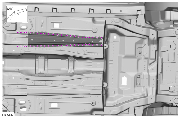
NOTE: Left hand (LH) side shown, right hand (RH) side similar.
NOTE: Factory welds may be substituted with resistance or metal inert gas (MIG) plug welds. Resistance welds may not be placed directly over original location. They must be placed adjacent to original location and match factory welds in quantity. Metal inert gas (MIG) plug welds must equal factory welds in both location and quantity.
NOTE: Adequately protect all adjacent areas against cutting, grinding and welding procedures.
-
Depower the SRS.
Refer to: Supplemental Restraint System (SRS) Depowering and Repowering (501-20B) .
-
If Required:
Dimensionally restore the vehicle to pre-damage condition.
Refer to: Body and Frame (501-26) .
-
Remove the underbody shield(s).
-
Remove the transmission.
Refer to: Transmission - 1.5L EcoBoost (118kW/160PS) – I4 (307-01A) .
Refer to: Transmission - 1.6L EcoBoost (132kW/180PS) – Sigma (307-01A) .
Refer to: Transmission - 2.0L EcoBoost (184kW/250PS) – MI4 (307-01A) .
Refer to: Transmission - 2.5L Duratec (125kW/170PS) (307-01A) .
Refer to: Transmission (308-03A) .
-
Relocate any fuel or brake lines away from the working area.
-
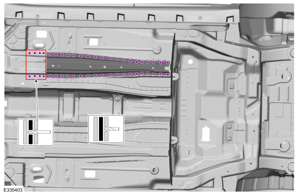
Remove the welds.
Use the General Equipment: Spot Weld Drill Bit
 |
-
NOTE: Pay particular attention the location of adhesives, sealers and NVH materials to aid in installation.
Remove the reinforcement.
 |
Installation
NOTICE: Battery electric vehicle (BEV), hybrid electric vehicle (HEV) and plug-in hybrid electric vehicle (PHEV) contain a high-voltage battery. Before cutting or welding near the high-voltage battery it must be removed to avoid damage.
NOTICE: The high-voltage battery in a battery electric vehicle (BEV), hybrid electric vehicle (HEV) or plug-in hybrid electric vehicle (PHEV) can be affected and damaged by excessively high temperatures. The temperature in some body shop paint booths can exceed 60° C (140° F). Therefore, during refinishing operations, the paint booth temperature must set at or below 60° C (140° F) with a bake time of 45 minutes or less. Temperatures in excess of 60° C (140° F) or bake durations longer than 45 minutes will require the high-voltage battery be removed from the vehicle prior to placing in the paint booth.
NOTICE: If refinishing cure temperatures exceed 60° C (140° F), the charge port light ring on plug-in vehicles must be removed.
NOTE: Left hand (LH) side shown, right hand (RH) side similar.
NOTE: Factory welds may be substituted with resistance or metal inert gas (MIG) plug welds. Resistance welds may not be placed directly over original location. They must be placed adjacent to original location and match factory welds in quantity. Metal inert gas (MIG) plug welds must equal factory welds in both location and quantity.
NOTE: Adequately protect all adjacent areas against cutting, grinding and welding procedures.
-
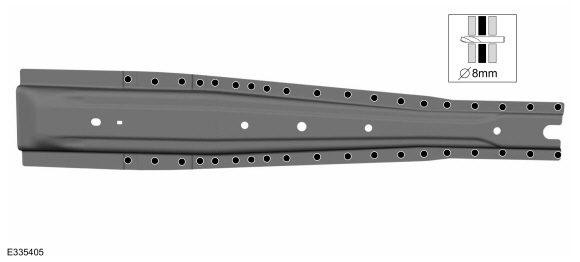
Drill plug weld holes in the replacement reinforcement.
Use the General Equipment: 8 mm Drill Bit
 |
-
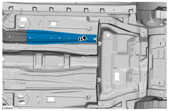
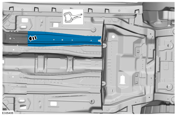
Install, properly position and clamp the lower reinforcement.
Use the General Equipment: Locking Pliers
 |
-
Install the welds.
Use the General Equipment: MIG/MAG Welding Equipment
 |
-
Dress all welds as required using typical metal finishing techniques.
-
Seam Sealing:
All seams must be sealed to production level.
Material: Seam Sealer / TA-2-B, 3M™ 08308, LORD Fusor® 803DTM
-
Refinish the entire repair using a Ford approved paint system.
-
Restore corrosion protection.
Refer to: Corrosion Prevention (501-25 Body Repairs - General Information, General Procedures).
-
Relocate any fuel or brake lines to original locations.
-
Install the transmission.
Refer to: Transmission - 1.5L EcoBoost (118kW/160PS) – I4 (307-01A) .
Refer to: Transmission - 1.6L EcoBoost (132kW/180PS) – Sigma (307-01A) .
Refer to: Transmission - 2.0L EcoBoost (184kW/250PS) – MI4 (307-01A) .
Refer to: Transmission - 2.5L Duratec (125kW/170PS) (307-01A) .
Refer to: Transmission (308-03A) .
-
Install the underbody shield(s).
-
Repower the SRS.
Refer to: Supplemental Restraint System (SRS) Depowering and Repowering (501-20B) .

 Front Floor Panel Side Member. Removal and Installation
Special Tool(s) /
General Equipment
Resistance Spotwelding Equipment
Scraper for Straight Edges
Hot Air Gun
8 mm Drill Bit
MIG/MAG Welding Equipment
Spot Weld Drill Bit
Locking Pliers
Materials
Name
Specification
Seam SealerTA-2-B, 3M™ 08308, LORD Fusor® 803DTM
-
Removal
NOTICE:
Battery electric vehicle (BEV), hybrid electric ve..
Other information:
Ford Fusion 2013–2020 Service Manual: Passenger Side Temperature Door Actuator. Removal and Installation
Removal NOTE: Removal steps in this procedure may contain installation details. WARNING: Before beginning any service procedure in this section, refer to Safety Warnings in section 100-00 General Information. Failure to follow this instruction may result in serious personal injury. Refer to: Climate Control System Health and Safety Precautions (100-00 General Informat..
Ford Fusion 2013–2020 Service Manual: Timing Adjustment. General Procedures
Special Tool(s) / General Equipment Flat-Bladed Screwdriver Adjustment NOTICE: A new frame assembly is not equipped with a motor. When a motor is not installed, and the frame is moved, the cables/mechanisms can experience free-play movement causing the timing to become out of adjustment. Before transferring a motor to a new frame assembly, the Timing Adjustment must be carried o..
Categories
- Manuals Home
- 2nd Generation Ford Fusion Owners Manual
- 2nd Generation Ford Fusion Service Manual
- Automatic Transmission Fluid Check - 1.5L EcoBoost™/2.0L EcoBoost™/2.5L. Automatic Transmission Fluid Check - 2.7L EcoBoost™
- Electrical
- Main Control Valve Body. Removal and Installation
- New on site
- Most important about car
Understanding Your Tire Pressure Monitoring System
The tire pressure monitoring system measures pressure in your road tires and sends the tire pressure readings to your vehicle. You can view the tire pressure readings through the information display. The low tire pressure warning light will turn on if the tire pressure is significantly low. Once the light is illuminated, your tires are under-inflated and need to be inflated to the manufacturer’s recommended tire pressure. Even if the light turns on and a short time later turns off, your tire pressure still needs to be checked.