Ford Fusion: Glass, Frames and Mechanisms / Rear Door Window Regulator. Removal and Installation
Ford Fusion 2013–2020 Service Manual / Body and Paint / Body and Paint / Glass, Frames and Mechanisms / Rear Door Window Regulator. Removal and Installation
Special Tool(s) / General Equipment
| Adhesive Tape |
Removal
NOTE: LH side shown, RH side similar.
NOTE: Removal steps in this procedure may contain installation details.
-
Remove the rear door speaker.
Refer to: Rear Door Speaker (415-00 Information and Entertainment System - General Information - Vehicles With: SYNC 3, Removal and Installation).
Refer to: Rear Door Speaker (415-00 Information and Entertainment System - General Information - Vehicles With: AM/FM/CD/SYNC) .
Refer to: Rear Door Speaker (415-00 Information and Entertainment System - General Information - Vehicles With: AM/FM/CD/SYNC/Sony Audio System) .
-
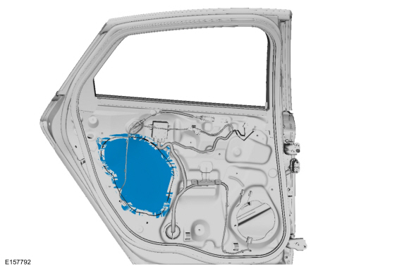
Remove the rear door watershield.
 |
-
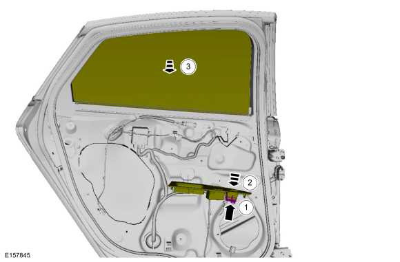
Lower the window glass to the full down position.
-
Install the rear window control switch.
-
Position the rear window control switch assembly.
-
Lower the window glass to the full down position.
-
Install the rear window control switch.
 |
-
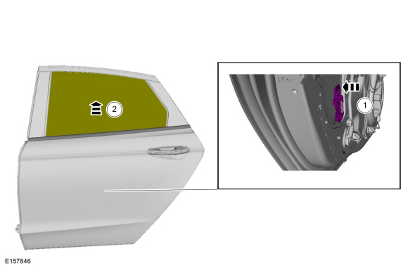
Raise the window glass to the full up position.
-
Release the rear door window clip.
-
Raise the window glass to the full up position.
-
Release the rear door window clip.
 |
-
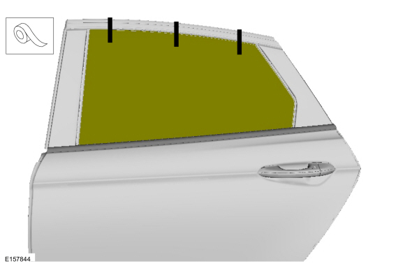
Raise the rear door window glass to full up and tape.
Use the General Equipment: Adhesive Tape
 |
-
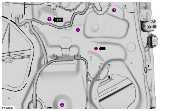
Remove the rear door window regulator bolt and nuts.
Torque: 93 lb.in (10.5 Nm)
 |
-
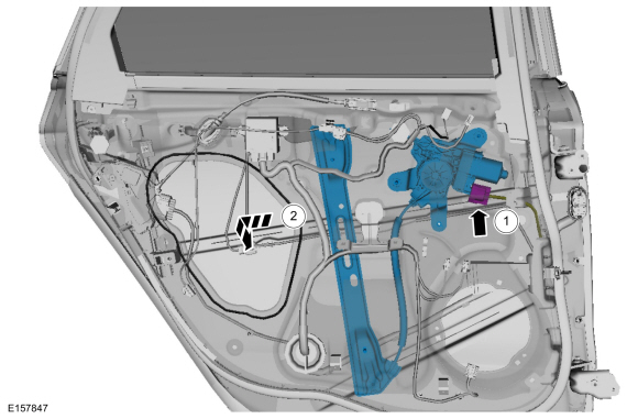
Remove the rear door window regulator.
-
Disconnect the electrical connector and position aside the wiring harness.
-
Remove the rear door window regulator.
-
Disconnect the electrical connector and position aside the wiring harness.
 |
Installation
-
To install, reverse the removal procedure.
-
Perform the power door window initialization.
Refer to: Power Door Window Initialization (501-11 Glass, Frames and Mechanisms, General Procedures).
 Front Door Window Regulator Motor. Removal and Installation
Removal
Remove the front door window regulator.
Refer to: Front Door Window Regulator (501-11 Glass, Frames and Mechanisms, Removal and Installation)...
 Rear Door Window Regulator Motor. Removal and Installation
Removal
Remove the rear door window regulator.
Refer to: Rear Door Window Regulator (501-11 Glass, Frames and Mechanisms, Removal and Installation)...
Other information:
Ford Fusion 2013–2020 Service Manual: Generator Current Sensor. Removal and Installation
Removal Disconnect the battery ground. Refer to: Battery Disconnect and Connect (414-01 Battery, Mounting and Cables) . NOTE: 2.5L shown, other engines similar. NOTE: Note the orientation and position of the generator current sensor tape tab...
Ford Fusion 2013–2020 Owners Manual: Adjusting the Headlamps
Vertical Aim Adjustment The headlamps on your vehicle are properly aimed at the assembly plant. If your vehicle has been in an accident, the alignment of your headlamps should be checked by your authorized dealer. Headlamp Aiming Target 8 feet (2...
Categories
- Manuals Home
- 2nd Generation Ford Fusion Owners Manual
- 2nd Generation Ford Fusion Service Manual
- Automatic Transmission - 6-Speed Automatic Transmission – 6F35
- Starter Motor. Removal and Installation
- Engine - 1.5L EcoBoost (118kW/160PS) – I4
- New on site
- Most important about car
Child Safety Locks
When these locks are set, the rear doors cannot be opened from the inside.

Copyright © 2026 www.fofusion2.com