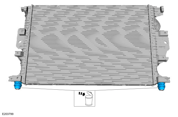
Ford Fusion: Engine Cooling - 1.5L EcoBoost (118kW/160PS) – I4 / Radiator. Removal and Installation
Ford Fusion 2013–2020 Service Manual / Powertrain / Engine / Engine Cooling - 1.5L EcoBoost (118kW/160PS) – I4 / Radiator. Removal and Installation
Special Tool(s) / General Equipment
| Hose Clamp Remover/Installer |
Removal
NOTE: Removal steps in this procedure may contain installation details.
-
Refer to: Engine Cooling System Health and Safety Precautions (100-00 General Information, Description and Operation).
-
Remove the CAC radiator.
Refer to: Charge Air Cooler (CAC) Radiator (303-12A Intake Air Distribution and Filtering - 1.5L EcoBoost (118kW/160PS) – I4, Removal and Installation).
-
Remove the air cleaner.
Refer to: Air Cleaner (303-12A Intake Air Distribution and Filtering - 1.5L EcoBoost (118kW/160PS) – I4, Removal and Installation).
-
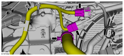
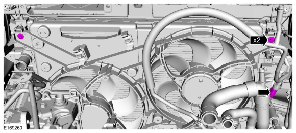
Disconnect the electrical connectors, release the clamp and disconnect the upper radiator hose.
Use the General Equipment: Hose Clamp Remover/Installer
 |
-
Depress the tab and disconnect the coolant tube.
 |
-
Remove the bolt and position the transmission fluid cooler aside.
Torque: 44 lb.in (5 Nm)
 |
-
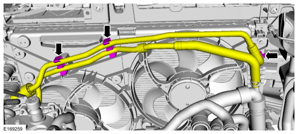
Release the clamp and disconnect the coolant hose. Detach the hoses from the retainers.
Use the General Equipment: Hose Clamp Remover/Installer
 |
-
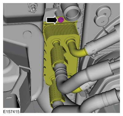
Disconnect the A/C pressure switch electrical connector and remove the bolts.
Torque: 53 lb.in (6 Nm)
 |
-
Remove the cooling fan motor and shroud.
-
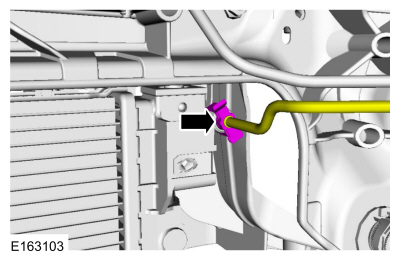
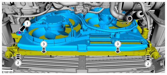
Remove the bolt.
Torque: 53 lb.in (6 Nm)
-
Position the radiator toward the front of the vehicle.
-
Remove the cooling fan motor and shroud.
-
Remove the bolt.
 |
-
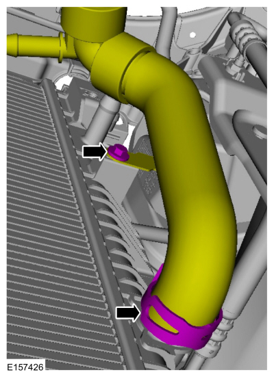
Remove the bolt, release the clamp and disconnect the lower radiator hose.
Use the General Equipment: Hose Clamp Remover/Installer
Torque: 62 lb.in (7 Nm)
 |
-
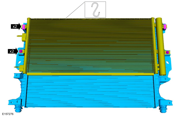
Support the A/C condenser, remove the bolts and the radiator from the vehicle.
Torque: 53 lb.in (6 Nm)
 |
-
Remove and discard the radiator lower isolators.
 |
Installation
-
NOTE: Install new radiator lower isolators.
To install, reverse the removal procedure.
 Degas Bottle. Removal and Installation
Special Tool(s) /
General Equipment
Hose Clamp(s)
Removal
NOTE:
Removal steps in this procedure may contain installation details.
WARNING:
Before beginning any service procedure in this
section, refer to Safety Warnings in section 100-00 General Information...
 Transmission Fluid Heater Coolant Control Valve. Removal and Installation
Special Tool(s) /
General Equipment
Hose Clamp(s)
Hose Clamp Remover/Installer
Removal
Remove the battery tray.
Refer to: Battery Tray (414-01 Battery, Mounting and Cables, Removal and Installation)...
Other information:
Ford Fusion 2013–2020 Service Manual: Engine. Assembly
Special Tool(s) / General Equipment 100-002 (TOOL-4201-C) Holding Fixture with Dial Indicator Gauge 300-OTC1819E2,200# Floor Crane, Fold Away 303-103 (T74P-6375-A) Holding Tool, FlywheelT74P-77000-ATKIT-2009TC-F 303-1097Locking Tool, Variable Camshaft Timing Oil Control UnitTKIT-2010B-FLMTKIT-2010B-ROW 303-1502Lifting Device EngineTKIT-2012A-FLTKIT-2012A-ROW ..
Ford Fusion 2013–2020 Service Manual: Rear Side Member Reinforcement Panel. Removal and Installation
Special Tool(s) / General Equipment Resistance Spotwelding Equipment Hot Air Gun Spot Weld Drill Bit Locking Pliers Materials Name Specification Metal Bonding AdhesiveTA-1, TA-1-B, 3M™ 08115, LORD Fusor® 108B - Removal NOTICE: Battery electric vehicle (BEV), hybrid electric vehicle (HEV) and plug-in hybrid electric vehicle (PHEV) contain a hi..
Categories
- Manuals Home
- 2nd Generation Ford Fusion Owners Manual
- 2nd Generation Ford Fusion Service Manual
- Cylinder Head. Removal and Installation
- Engine - 1.5L EcoBoost (118kW/160PS) – I4
- Starter Motor. Removal and Installation
- New on site
- Most important about car
Direction Indicators. Interior Lamps
Direction Indicators

Push the lever up or down to use the direction indicators.
Copyright © 2026 www.fofusion2.com