Ford Fusion: Steering Wheel and Column Electrical Components / Steering Wheel and Column Electrical Components - System Operation and Component Description. Description and Operation
System Operation
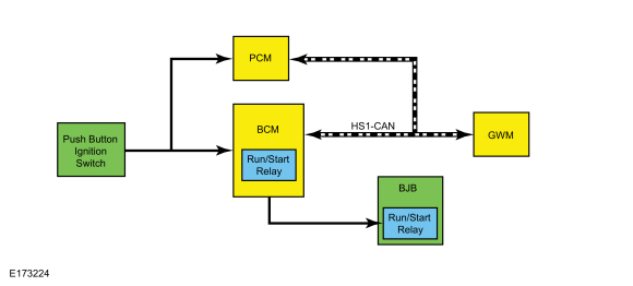
System Diagram - Push Button Start
.jpg)
| Item | Description |
|---|---|
| 1 | HS1-CAN |
| 2 | GWM |
| 3 | PCM |
| 4 | BJB |
| 5 | Run/Start Relay |
| 6 | Push Button Ignition Switch |
| 7 | BCM |
| 8 | Run/Start Relay |
Network Message Chart - Push Button Start
GWM Module Network Input Messages
| Broadcast Message | Originating Module | Message Purpose |
|---|---|---|
| Ignition status | BCM | This message informs the GWM of the current ignition status; off, run, start, unknown or invalid. |
PCM Module Network Input Messages
| Broadcast Message | Originating Module | Message Purpose |
|---|---|---|
| Ignition status | BCM | This message informs the PCM GWM BCM of the current ignition status; off, run, start, unknown or invalid. |
Push Button Ignition Switch
The push button ignition switch is used to control the ON, OFF and START ignition modes.
The BCM
monitors one circuit for voltage from the ignition switch and sends a
voltage signal on a second circuit to the ignition switch to monitor
requests to turn the ignition on, off or to start the vehicle. When the
button is pressed, one circuit routes battery voltage to the BCM while the voltage signal from the BCM
on the second circuit is routed to ground, indicating a request to
change the ignition state. Changing the ignition state from the OFF mode
works in conjunction with the PATS. A valid programmed key is required to change the ignition from OFF to ON. For additional PATS information,
Refer to: Passive Anti-Theft System (PATS) (419-01 Passive Anti-Theft System (PATS) - Vehicles With: Push Button Start)
.
Refer to the following table for information about achieving the various ignition states.
| Ignition Entry Condition | Desired Ignition Mode | Action To Take |
|---|---|---|
| Off | ON (engine off) | Press the START/STOP button without applying the brake pedal. |
| Any ignition mode | START | Apply the brake pedal and then press the START/STOP button. |
| On (engine off) | OFF | Press the START/STOP button. |
| On (engine running) | OFF | Press and hold the START/STOP button. |
The BCM must recognize a programmed key before it changes the ignition state from OFF.
Ignition Mode LED Indicator
The ignition mode LED indicates the ignition mode of the vehicle. The BCM controls the voltage to the ignition mode LED indicator. Refer to the following table.
| Ignition Mode | Ignition Mode LED Indicator |
|---|---|
| Off | Off |
| On (engine off) | Flashing |
| On (engine running) | On |
OFF
The BCM controls the relays providing voltage to the vehicle electrical systems. When the ignition is in the ON mode, a single press and release of the START/STOP button changes the ignition to the OFF mode. No programmed key is required to change the ignition to the OFF mode when the vehicle is running.
If the vehicle is in motion, a momentary press of the START/STOP button does not shut the vehicle off. If the vehicle is moving, the START/STOP button must be pressed and held for longer than one second to turn the ignition off.
When the BCM changes the ignition state to OFF, it communicates the ignition mode to the other modules by sending an ignition status message over the CAN.
ON
The BCM
must recognize a valid programmed key before it changes the ignition
state out of OFF. When the START/STOP button is pressed when the
ignition is off, the BCM checks the vehicle for a valid programmed key as part of the PATS function. If no valid programmed key is detected, the ignition remains off. For additional PATS information,
Refer to: Passive Anti-Theft System (PATS) (419-01 Passive Anti-Theft System (PATS) - Vehicles With: Push Button Start)
.
When the ignition is in the ON mode, the BCM activates the run/start relays to provide voltage to the vehicle electrical systems and communicates the ignition mode to the other modules by sending an ignition status message over the CAN.
When the vehicle enters ON mode, multiple indicators in the IPC prove out and the IPC displays the gear selection and the vehicle mileage.
START
The vehicle temporarily goes into START mode if a valid programmed key is detected inside the vehicle, and the brake pedal is applied while the START/STOP button is pressed.
In addition to activating the run/start relays, the BCM communicates the ignition mode to the other modules by sending an ignition status message over the CAN.
Once the ignition has entered START mode, the indicator in the ignition switch illuminates.
The engine can be started from any ignition mode.
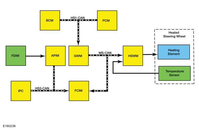
System Diagram - Heated Steering Wheel
Network Message Chart - Heated Steering Wheel
HSWM Network Input Messages
| Broadcast Message | Originating Module | Message Purpose |
|---|---|---|
| Engine power status | PCM | This message indicates to the HSWM whether the engine is running. |
| Ignition status | BCM | Indicates which ignition state is active. |
| Transport mode | BCM | Message is used to reduce the drain on the battery during long periods when the vehicle is not used, such as shipping from the factory to the dealership. |
| Steering wheel heat request | FCIM | Message is used to activate the heated steering wheel when the soft button is pressed on the FDIM, or when the conditions are met to activate the heated steering wheel (and heated seats) during a remote start. |
FCIM Module Network Input Messages
| Broadcast Message | Originating Module | Message Purpose |
|---|---|---|
| Heated steering wheel button status | APIM | This message informs the FCIM that the heated steering wheel soft button was pressed on the FDIM. |
| Ambient exterior temperature data | IPC | This message is used by the FCIM when determining if outside conditions are cold enough to request the heated steering wheel be activated during remote start operation. |
Heated Steering Wheel
When the HSWM receives a request to heat the steering wheel, the HSWM applies voltage and ground to the steering wheel heating elements (integral to the steering wheel) to heat the steering wheel to a temperature of approximately 28-34°C (82-94°F). The heated steering wheel temperature is maintained by the HSWM using a temperature sensor in the steering wheel.
The HSWM is designed to remain on, heating the steering wheel and maintaining the temperature until switched off on the FDIM or the ignition is turned off.
The controls and indicators for the heated steering wheel system are located on the FDIM (touchscreen) only. The FDIM does not communicate on any network and is connected directly to the APIM.
Remote Start System
The heated steering wheel system (along with the heated front seats) may be configured through the message center to activate when the remote start feature is used, based on outside air temperature. During remote start, the outside air temperature is continually evaluated by the HVAC system. The heated steering wheel system activation changes if the outside air changes from cold to moderate or warm temperatures or back from moderate or warm to cold temperatures.
Field Effect Transistor (FET) Protection
A
Field Effect Transistor (FET) is a type of transistor that, when used
with module software, monitors and controls current flow on module
outputs. The Field Effect Transistor (FET) protection strategy prevents
module damage in the event of excessive current flow. For additional
information about Field Effect Transistor (FET) protection,
Refer to: Module Controlled Functions - System Operation and Component Description (419-10 Multifunction Electronic Modules, Description and Operation).
Component Description
Multifunction Switch
The
multifunction switch is a multiple position switch controlled by a
lever. The multifunction switch controls the turn signal, headlamp
low/high beam and headlamp dimmer/flash-to-pass functions.
Refer to: Exterior Lighting (417-01 Exterior Lighting)
.
Wiper and Washer Switch
The
wiper and washer switch is a multiple position switch controlled by a
lever. The wiper and washer switch controls the front windshield wipers
and washers.
Refer to: Wipers and Washers (501-16 Wipers and Washers)
.
Steering Wheel Switches
The steering wheel switches are comprised of an upper and lower switch cluster mounted on each side of the steering wheel, facing the driver. The upper and lower switch clusters are integrated into a single switch and cannot be serviced separately.
The LH upper switch cluster controls the message center display.
Refer to: Message Center - Overview (413-01 Instrumentation, Message Center and Warning Chimes, Description and Operation).
The LH lower switch cluster controls the cruise control system.
Refer to: Cruise Control (419-03 Cruise Control)
.
The RH upper and lower switch clusters control the audio and SYNC® systems. Refer to the appropriate section in Group 415 for the procedure.
Push Button Ignition Switch
The ignition switch is a momentary dual contact switch that provides input to the BCM and PCM.
Both sets of contacts are normally open and receive voltage at all times. When the ignition switch is pressed, one set of contacts supplies ground to the BCM and the other set of contacts supplies voltage to the BCM and the PCM.
The ignition switch has a LED for switch illumination.
BCM
The BCM determines the vehicle ignition mode based on the ignition switch input and the stoplamp switch input. The BCM communicates the ignition mode to the other modules over the CAN. The BCM
monitors the ignition switch input and the ignition mode outputs. If a
fault is detected in the ignition system, Diagnostic Trouble Codes
(DTCs) are set in the BCM.
Refer to: Module Controlled Functions - Component Location (419-10 Multifunction Electronic Modules, Description and Operation).
HSWM
The HSWM controls the steering wheel heating elements. The HSWM uses the steering wheel temperature sensor to maintain the steering wheel temperature. The HSWM is designed to remain on, heating the steering wheel and maintaining temperature until switched off on the FDIM or the ignition is turned off.
The HSWM requires PMI when replaced.
FDIM
The controls and indicators for the heated steering wheel system are located in the FDIM (touchscreen) only. For additional information about the FDIM, Refer to the appropriate section in Group 415 for the procedure.
Steering Wheel
The steering wheel heater elements are integral to the steering wheel and cannot be serviced separately. The HSWM uses the steering wheel heater elements to heat the steering wheel.
The steering wheel temperature sensor is part of the steering wheel and cannot be serviced separately. The HSWM uses the steering wheel temperature sensor to monitor the steering wheel temperature.
 Steering Wheel and Column Electrical Components - Overview. Description and Operation
Steering Column Switches Overview
The
steering column switches are located on and around the steering column.
This enables the driver to control various vehicle functions and remain
focused on driving...
 Steering Wheel and Column Electrical Components. Diagnosis and Testing
DTC Charts
BCM
DTC Chart
Diagnostics in this manual assume a certain skill level and knowledge of Ford-specific diagnostic practices. REFER to: Diagnostic Methods (100-00 General Information, Description and Operation)...
Other information:
Ford Fusion 2013–2020 Service Manual: Evaporator Temperature Sensor. Removal and Installation
Removal NOTE: Removal steps in this procedure may contain installation details. WARNING: Before beginning any service procedure in this section, refer to Safety Warnings in section 100-00 General Information. Failure to follow this instruction may result in serious personal injury...
Ford Fusion 2013–2020 Service Manual: Charging System. Diagnosis and Testing
Inspection and Verification Verify the customer concern by operating the charging system. Before diagnosing or repairing the charging system inspect the following items: Check the battery for loose, damaged or corroded connections...
Categories
- Manuals Home
- 2nd Generation Ford Fusion Owners Manual
- 2nd Generation Ford Fusion Service Manual
- Intake Manifold. Removal and Installation
- Traction Control
- Garage Door Opener
- New on site
- Most important about car
Child Safety Locks
When these locks are set, the rear doors cannot be opened from the inside.
