Ford Fusion: Front Suspension / Front Strut and Spring Assembly. Removal and Installation
Removal
NOTICE:
Suspension fasteners are critical parts that affect the
performance of vital components and systems. Failure of these fasteners
may result in major service expense. Use the same or equivalent parts if
replacement is necessary. Do not use a replacement part of lesser
quality or substitute design. Tighten fasteners as specified.
-
Remove the wheel and tire.
Refer to: Wheel and Tire (204-04A Wheels and Tires, Removal and Installation).
-
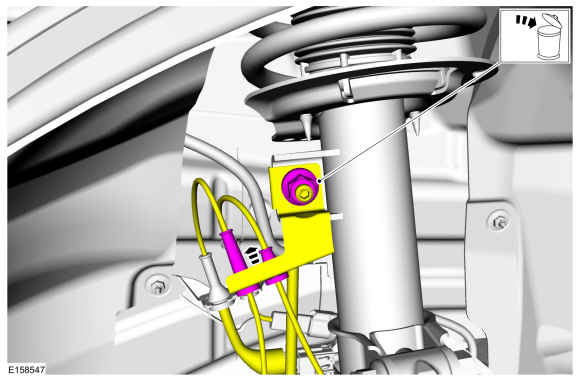
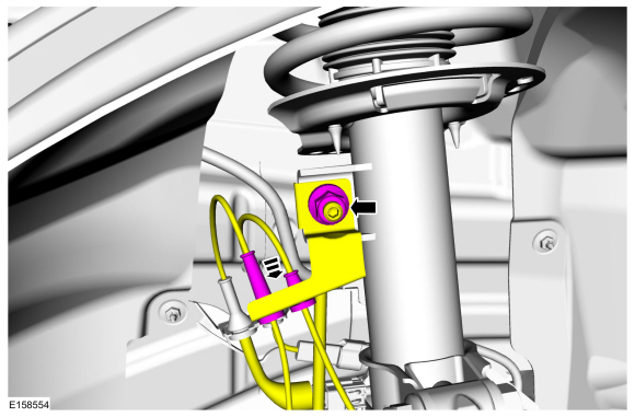
Remove the brake hose bracket bolt.
-
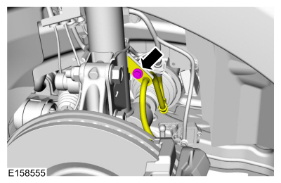
Remove and discard the upper stabilizer bar link nut and
position the stabilizer bar link and the wire harness bracket aside.
-
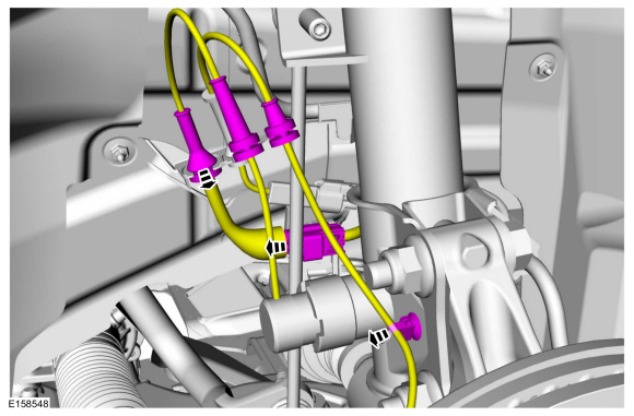
Unclip the 3 wire retainers.
-
NOTICE:
The front suspension height sensor must be
disconnected from the lower control arm prior to servicing suspension
components or damage to the suspension height sensor and/or the vehicle
dynamic suspension system may occur. The sensor will need to be
recalibrated after reassembly.
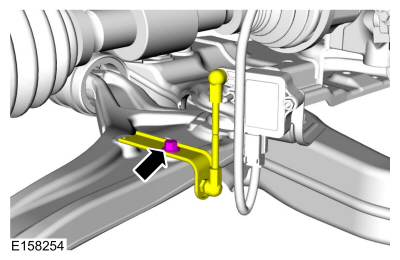
Remove the height sensor arm bracket bolt and position the height sensor arm bracket aside.
-
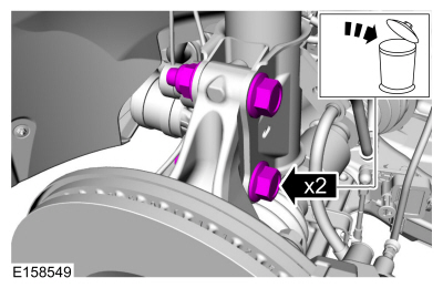
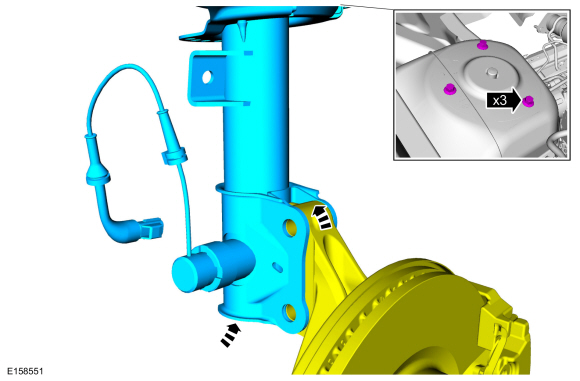
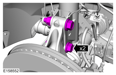
Remove and discard the 2 front strut and spring assembly-to-wheel knuckle bolts and nuts.
-
Remove the cowl panel grille.
Refer to: Cowl Panel Grille (501-02 Front End Body Panels, Removal and Installation).
-
Remove and discard the 3 front strut and spring assembly and remove the front strut and spring assembly.
Installation
-
Install the front strut and spring assembly and install the 3 new front strut and spring assembly nuts.
Torque:
26 lb.ft (35 Nm)
-
Install the cowl panel grille.
Refer to: Cowl Panel Grille (501-02 Front End Body Panels, Removal and Installation).
-
Install the 2 new front strut and spring assembly-to-wheel knuckle bolts and nuts.
Torque:
173 lb.ft (235 Nm)
-
Position the front height sensor arm brack and install the front height sensor arm bracket bolt.
Torque:
177 lb.in (20 Nm)
-
Clip the 3 wire retainers.
-
Position the wire harness bracket and stabilizer bar link and install the new upper stabilizer bar link nut.
Torque:
85 lb.ft (115 Nm)
-
Install the brake hose bracket bolt.
Torque:
159 lb.in (18 Nm)
-
Install the wheel and tire.
Refer to: Wheel and Tire (204-04A Wheels and Tires, Removal and Installation).
-
Check and if necessary adjust front camber.
Refer to: Front Camber Adjustment (204-00 Suspension System - General Information, General Procedures).
-
Calibrate the suspension system. Connect the scan tool
and carry out the Ride Height Calibration routine. Follow the scan tool
directions.
Removal
NOTICE:
Suspension fasteners are critical parts that affect the
performance of vital components and systems. Failure of these fasteners
may result in major service expense...
Special Tool(s) /
General Equipment
Hydraulic Press
Removal
Remove the front wheel bearing and wheel hub.
Refer to: Front Wheel Bearing and Wheel Hub (204-01 Front Suspension, Removal and Installation)...
Other information:
Removal
Remove the upper rain sensor cover.
Squeeze the upper rain sensor cover.
Remove the upper rain sensor cover.
Remove the lower rain sensor cover.
Release the tabs.
Remove the lower rain sensor cover...
Check
NOTE:
Refer to the appropriate Section 303-01 for the specification.
Measure the cylinder bore at the top, middle and bottom
of piston ring travel in 2 directions as indicated. Verify the cylinder
bore is within the wear limit. The difference indicates the cylinder
bore taper...


 Front Stabilizer Bar Link. Removal and Installation
 Wheel Studs. Removal and Installation