Ford Fusion: Information and Entertainment System - General Information - Vehicles With: SYNC 3 / Front Controls Interface Module (FCIM) - Police. Removal and Installation
Ford Fusion 2013–2020 Service Manual / Electrical / Information and Entertainment Systems / Information and Entertainment System - General Information - Vehicles With: SYNC 3 / Front Controls Interface Module (FCIM) - Police. Removal and Installation
Special Tool(s) / General Equipment
| Interior Trim Remover |
Removal
NOTE: Removal steps in this procedure may contain installation details.
-
NOTE: If installing a new module, it is necessary to upload the module configuration information to the scan tool prior to removing the module. This information must be downloaded into the new module after installation.
Using a diagnostic scan tool, begin the PMI process for the FCIM following the on-screen instructions.
-
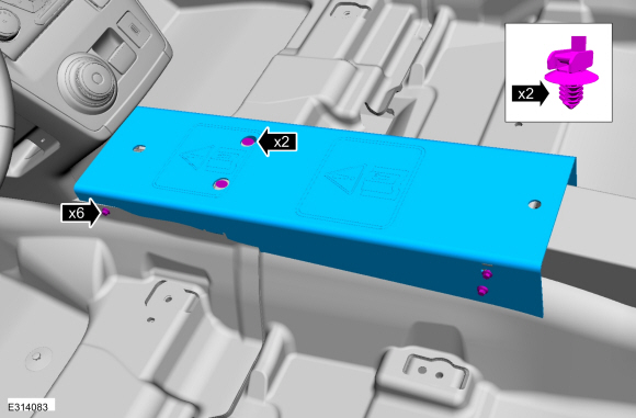
Remove the bolts, nuts, release the harenss retainers and remove the plate.
Torque: 55 lb.in (6.2 Nm)
 |
-
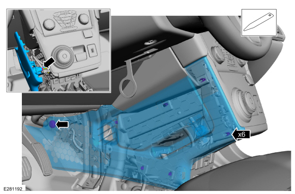
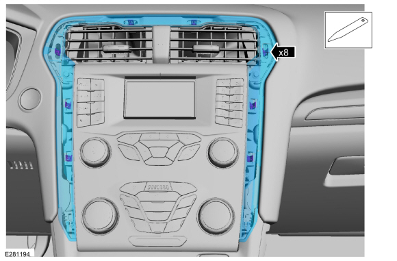
Remove the screw, release the clips, disconnect the electrical connector and remove the LH center instrument panel trim panel.
Use the General Equipment: Interior Trim Remover
 |
-
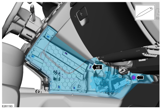
Remove the screw, release the clips and remove the RH center instrument panel trim panel.
Use the General Equipment: Interior Trim Remover
 |
-
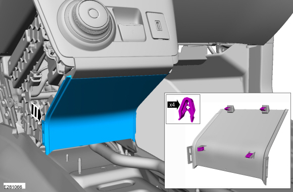
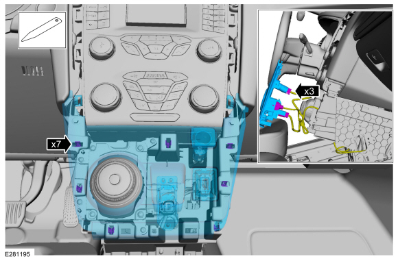
Release the clips and remove the center lower trim panel.
 |
-
Release the clips and remove the FCIM bezel.
Use the General Equipment: Interior Trim Remover
 |
-
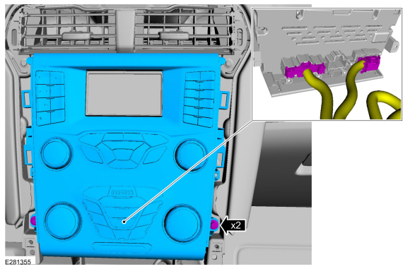
Release the clips, disconnect the electrical connectors and remove the GSM bezel.
Use the General Equipment: Interior Trim Remover
 |
-
Remove the bolts and the FCIM.
-
Disconnect the electrical connectors.
Torque: 22 lb.in (2.5 Nm)
-
Disconnect the electrical connectors.
 |
Installation
-
To install, reverse the removal procedure.
-
NOTE: This step is only necessary when installing a new component.
Using a diagnostic scan tool, complete the PMI process for the FCDIM FCIM following the on-screen instructions.
 Front Controls Interface Module (FCIM). Removal and Installation
Special Tool(s) /
General Equipment
Interior Trim Remover
Removal
NOTE:
Removal steps in this procedure may contain installation details...
 Front Display Interface Module (FDIM). Removal and Installation
Removal
NOTE:
Removal steps in this procedure may contain installation details.
Remove the FCIM.
Refer to: Front Controls Interface Module (FCIM) (415-00C)
...
Other information:
Ford Fusion 2013–2020 Service Manual: Safety Precautions - Overview. Description and Operation
Overview Before beginning any service procedure in this manual, refer to health and safety warnings in section 100-00 General Information. Failure to follow this instruction may result in serious personal injury. WARNING: Before servicing any tire, ask the customer if anyone injected a tire sealant into the tire...
News: Ford Recalls Nearly 60,000 Vehicles Including Fusion for Fire Risk
Date: October 16, 2025 Automaker Ford has announced a recall affecting approximately 59,006 vehicles in the United States, among them some units of the Fusion model. The decision follows identification of a fault in the engine block heater which may develop a crack, allowing coolant to leak and possibly trigger a short-circuit under the hood...
Categories
- Manuals Home
- 2nd Generation Ford Fusion Owners Manual
- 2nd Generation Ford Fusion Service Manual
- Electrical
- Main Control Valve Body. Removal and Installation
- Memory Function
- New on site
- Most important about car
Direction Indicators. Interior Lamps
Direction Indicators

Push the lever up or down to use the direction indicators.
Copyright © 2026 www.fofusion2.com