Ford Fusion: Bumpers / Front Bumper Cover. Disassembly and Assembly
Ford Fusion 2013–2020 Service Manual / Body and Paint / Body and Paint / Bumpers / Front Bumper Cover. Disassembly and Assembly
Special Tool(s) / General Equipment
| Hot Air Gun |
DISASSEMBLY
NOTE: Removal steps in this procedure may contain installation details.
-
Remove the front bumper cover.
Refer to: Front Bumper Cover (501-19 Bumpers, Removal and Installation).
-
Remove the front fog lamps.
Refer to: Front Fog Lamp (417-01 Exterior Lighting, Removal and Installation).
-
Remove the front parking aid sensors, active park assist sensors and associated wiring.
Refer to: Front Parking Aid Sensor (413-13A Parking Aid, Removal and Installation).
Refer to: Front Active Park Assist Sensors (413-13B Parking Aid - Vehicles With: Active Park Assist, Removal and Installation).
-
Remove the ambient air temperature sensor.
Refer to: Ambient Air Temperature Sensor (412-00 Climate Control System - General Information, Removal and Installation).
-
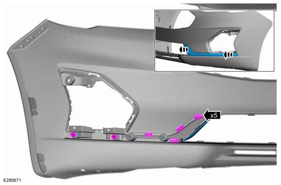
Separate the harness guides and remove the front bumper cover harness.
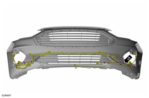 |
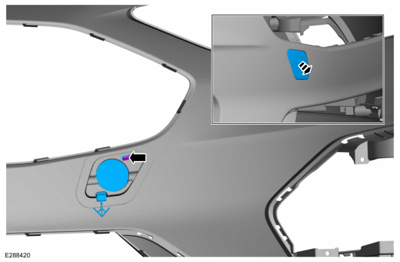
-
On both sides.
Remove the push pin and the front bumper cover-to-fender bracket.
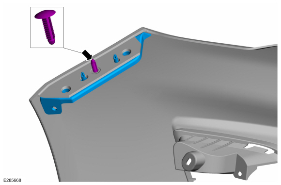 |
-
Release the tabs and remove the lower radiator grille.
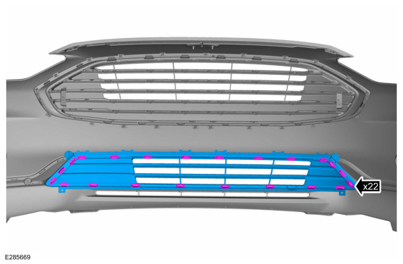 |
-
Release the tabs and remove the upper radiator grille.
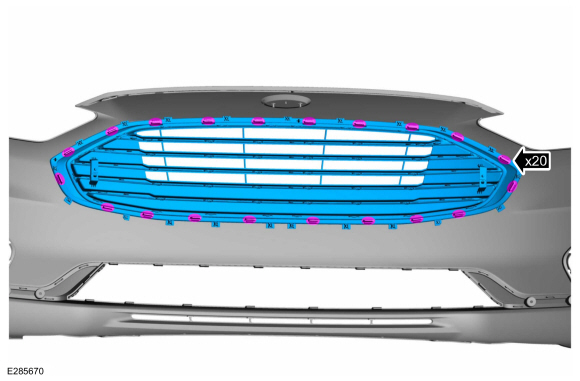 |
-
Release the tabs and remove the fog lamp bezels.
 |
-
Release the tab and remove the tow hook cover.
 |
-
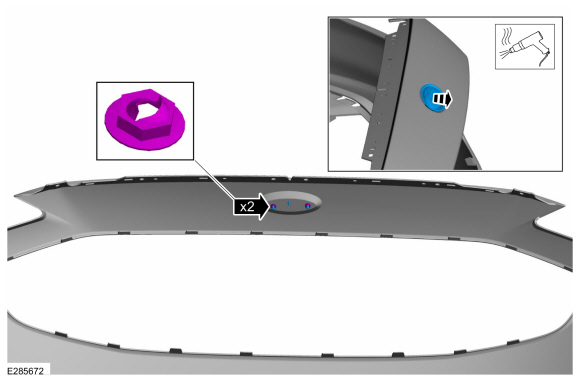
Remove the push nuts and the front bumper cover emblem.
Use the General Equipment: Hot Air Gun
 |
ASSEMBLY
-
To assemble, reverse the disassembly procedure.
 Rear Bumper Cover. Removal and Installation
Special Tool(s) /
General Equipment
Interior Trim Remover
Removal
NOTE:
Removal steps in this procedure may contain installation details...
 Rear Bumper Cover. Disassembly and Assembly
DISASSEMBLY
NOTE:
Removal steps in this procedure may contain installation details.
Remove the rear bumper cover.
Refer to: Rear Bumper Cover (501-19 Bumpers, Removal and Installation)...
Other information:
Ford Fusion 2013–2020 Service Manual: Body Control Module (BCM). Removal and Installation
Special Tool(s) / General Equipment Interior Trim Remover Removal All vehicles NOTE: Removal steps in this procedure may contain installation details. NOTE: If the BCM did not respond to the diagnostic scan tool, As-Built Data may need to be entered as part of the repair...
Ford Fusion 2013–2020 Service Manual: Rear Suspension Bracket Reinforcement. Removal and Installation
Special Tool(s) / General Equipment 8 mm Drill Bit MIG/MAG Welding Equipment Spot Weld Drill Bit Locking Pliers Removal NOTICE: Battery electric vehicle (BEV), hybrid electric vehicle (HEV) and plug-in hybrid electric vehicle (PHEV) contain a high-voltage battery...
Categories
- Manuals Home
- 2nd Generation Ford Fusion Owners Manual
- 2nd Generation Ford Fusion Service Manual
- Under Hood Overview - 1.5L EcoBoost™, 2.0L EcoBoost™, 2.5L, 2.7L EcoBoost™
- Pre-Collision Assist (IF EQUIPPED)
- Transmission - 1.5L EcoBoost (118kW/160PS) – I4. Removal and Installation
- New on site
- Most important about car
Fuel Quality
Choosing the Right Fuel
Your vehicle is designed to operate on regular unleaded gasoline with a minimum pump (R+M)/2 octane rating of 87.
Copyright © 2026 www.fofusion2.com