Ford Fusion: Rear Suspension / Rear Stabilizer Bar. Removal and Installation
Removal
NOTICE: Suspension fasteners are critical parts that affect the performance of vital components and systems. Failure of these fasteners may result in major service expense. Use the same or equivalent parts if replacement is necessary. Do not use a replacement part of lesser quality or substitute design. Tighten fasteners as specified.
-
With the vehicle in NEUTRAL, position it on a hoist.
Refer to: Jacking and Lifting - Overview (100-02 Jacking and Lifting, Description and Operation).
-
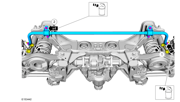
NOTICE: Do not use power tools to remove or install the stabilizer bar link nuts. Damage to the stabilizer bar link ball joints and boots may occur.
NOTE: AWD vehicle shown, FWD vehicle similar.
-
Remove and discard the rear stabilizer bar link
upper nuts and disconnect the rear stabilizer bar links from the rear
stabilizer bar.
-
Remove and discard the rear stabilizer bar bracket bolts and remove the rear stabilizer bar.
-
Remove and discard the rear stabilizer bar link
upper nuts and disconnect the rear stabilizer bar links from the rear
stabilizer bar.
 |
-
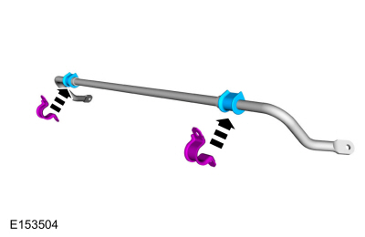
NOTICE: Do not use any lubrication on the stabilizer bar or the bushings or damage to the bushings may occur.
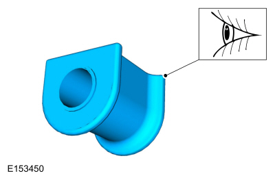
NOTE: Stabilizer bar bushings must be installed with slits facing the front of the vehicle.
Inspect and, if necessary, install new stabilizer bar bushings.
 |
Installation
-
NOTE: Apply water to the brackets to aid in installation.
Press the rear stabilizer bar brackets in place onto the rear stabilizer bar bushings.
 |
-
-
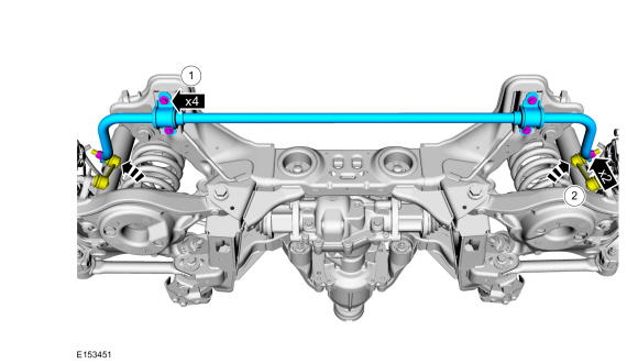
Position the rear stabilizer bar and install the new rear stabilizer bar bracket bolts.
Torque: 52 lb.ft (70 Nm)
-
Position the rear stabilizer bar links and install the new rear stabilizer bar link nuts.
Torque: 85 lb.ft (115 Nm)
-
Position the rear stabilizer bar and install the new rear stabilizer bar bracket bolts.
 |
 Wheel Bearing and Wheel Hub - FWD. Removal and Installation
Removal
NOTICE:
Suspension fasteners are critical parts that affect the
performance of vital components and systems. Failure of these fasteners
may result in major service expense...
 Rear Stabilizer Bar Link. Removal and Installation
Removal
NOTE:
Removal steps in this procedure may contain installation details.
With the vehicle in NEUTRAL, position it on a hoist.
Refer to: Jacking and Lifting - Overview (100-02 Jacking and Lifting, Description and Operation)...
Other information:
Ford Fusion 2013–2020 Service Manual: Quick Release Coupling. General Procedures
Disconnect NOTE: When reusing liquid or vapor tube connections, make sure to use compressed air to remove any foreign material from the connector retaining clip area before separating from the tube or damage to the tube or connector retaining clip may occur...
Ford Fusion 2013–2020 Service Manual: Active Grille Shutter. Removal and Installation
Removal NOTE: Removal steps in this procedure may contain installation details. Remove the front bumper cover. Refer to: Front Bumper Cover (501-19 Bumpers, Disassembly and Assembly). On both sides. Remove the pin-type retainers...
Categories
- Manuals Home
- 2nd Generation Ford Fusion Owners Manual
- 2nd Generation Ford Fusion Service Manual
- Load Carrying
- Traction Control
- Automatic Transmission Fluid Check - 1.5L EcoBoost™/2.0L EcoBoost™/2.5L. Automatic Transmission Fluid Check - 2.7L EcoBoost™
- New on site
- Most important about car
Fuel Quality
Choosing the Right Fuel
Your vehicle is designed to operate on regular unleaded gasoline with a minimum pump (R+M)/2 octane rating of 87.