Ford Fusion: Engine Cooling - 1.5L EcoBoost (118kW/160PS) – I4 / Engine Cooling. Diagnosis and Testing
Special Tool(s)

|
3-Way HD Antifreeze Coolant Test Kit 328-2050-62291 or equivalent |

|
Coolant/Battery Refractometer ROB75240 or equivalent |

|
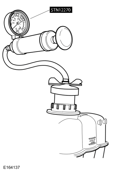
Pressure Tester STN12270 or equivalent |

|
UView Combustion Leak Tester UVU560000-R |
NOTICE: Use the correct coolant. Do not mix coolant types. Mixing coolant types may degrade the coolant corrosion protection and may damage the engine or cooling system. For the correct coolant specified for this vehicle, refer to Specifications.
|
REFER to: Specifications (303-03A Engine Cooling - 1.5L EcoBoost (118kW/160PS) – I4, Specifications). |
DTC Chart
 WARNING:
Before beginning any service procedure in this section,
refer to Safety Warnings in section 100-00 General Information. Failure
to follow this instruction may result in serious personal injury.
WARNING:
Before beginning any service procedure in this section,
refer to Safety Warnings in section 100-00 General Information. Failure
to follow this instruction may result in serious personal injury.
REFER to: Engine Cooling System Health and Safety Precautions (100-00 General Information, Description and Operation).
Diagnostics in this manual assume a certain skill level and knowledge of Ford-specific diagnostic practices.
REFER to: Diagnostic Methods (100-00 General Information, Description and Operation).
PCM DTC Chart
| DTC | Description | Action |
| P0125 | Insufficient Coolant Temp For Closed Loop Fuel Control | GO to Pinpoint Test C |
| P0128 | Coolant Thermostat (Coolant Temp Below Thermostat Regulating Temperature) | GO to Pinpoint Test C |
| P0217 | Engine Coolant Overtemperature Condition | GO to Pinpoint Test B |
| P0480 | Fan 1 Control Circuit | Refer to Powertrain Control/Emissions Diagnosis (PC/ED) manual. |
| P0481 | Fan 2 Control Circuit | Refer to Powertrain Control/Emissions Diagnosis (PC/ED) manual. |
| P0691 | Fan 1 Control Circuit Low | Refer to Powertrain Control/Emissions Diagnosis (PC/ED) manual. |
| P0692 | Fan 1 Control Circuit High | Refer to Powertrain Control/Emissions Diagnosis (PC/ED) manual. |
| P0693 | Fan 2 Control Circuit Low | Refer to Powertrain Control/Emissions Diagnosis (PC/ED) manual. |
| P0694 | Fan 2 Control Circuit High | Refer to Powertrain Control/Emissions Diagnosis (PC/ED) manual. |
| P1285 | Cylinder Head Overtemperature Condition | GO to Pinpoint Test B |
| P1299 | Cylinder Head Overtemperature Protection Active | GO to Pinpoint Test B |
| P2681 | Engine Coolant Bypass Valve "A" Control Circuit/Open |
REFER to: Transmission Cooling (307-02A Transmission Cooling - 6-Speed Automatic Transmission – 6F35, Diagnosis and Testing). |
| P2683 | Engine Coolant Bypass Valve "A" Control Circuit High |
REFER to: Transmission Cooling (307-02A Transmission Cooling - 6-Speed Automatic Transmission – 6F35, Diagnosis and Testing). |
| All Other PCM Diagnostic Trouble Codes (DTCs) | — |
Inspection and Verification
 WARNING:
Always allow the engine to cool before opening the cooling
system. Do not unscrew the coolant pressure relief cap when the engine
is operating or the cooling system is hot. The cooling system is under
pressure; steam and hot liquid can come out forcefully when the cap is
loosened slightly. Failure to follow these instructions may result in
serious personal injury.
WARNING:
Always allow the engine to cool before opening the cooling
system. Do not unscrew the coolant pressure relief cap when the engine
is operating or the cooling system is hot. The cooling system is under
pressure; steam and hot liquid can come out forcefully when the cap is
loosened slightly. Failure to follow these instructions may result in
serious personal injury.
NOTE: During normal vehicle operation, coolant can change color. As long as the engine coolant is clear and uncontaminated, this color change does not indicate the engine coolant has degraded nor does it require the engine coolant to be drained, the system to be flushed, or the engine coolant to be replaced.
NOTE: Vehicles have a pressure relief cap on the degas bottle and no radiator cap.
-
Verify the customer concern.
-
Visually check the engine coolant level at the degas bottle when the system is cold.
-
Make sure the pressure relief cap is installed correctly.
-
Record any cooling system Diagnostic Trouble Codes (DTCs) retrieved. Refer to the PCM
DTC chart in this section for DTC descriptions.
-
NOTE: Take note of any coolant odor or steam coming from cooling system components.
If the system coolant is filled correctly and no Diagnostic Trouble Codes (DTCs) associated with fail-safe cooling are retrieved, verify the customer concern by operating the engine to duplicate the condition.
-
Visually inspect for obvious signs of any mechanical or electrical damage.
Visual Inspection Chart
| Mechanical | Electrical |
|---|---|
|
|
-
If the inspection reveals an obvious concern that can be readily identified, repair it as necessary.
-
Inspect the coolant condition.
-
Inspect the coolant color.
-
A darker orange with the presence of debris could
indicate a commercially available stop leak may have been used and could
result in loss of coolant flow to critical parts of the engine. If
sediment is present, flush the system and refill with the correct
mixture of distilled water and the relevant Motorcraft® Concentrated
Antifreeze/Coolant.
REFER to: Engine Cooling System Flushing (303-03A Engine Cooling - 1.5L EcoBoost (118kW/160PS) – I4, General Procedures).
-
A light or reddish brown color indicates that rust
may be present in the cooling system. Flush the system and refill with
the correct mixture of distilled water the relevant Motorcraft®
Concentrated Antifreeze/Coolant.
REFER to: Engine Cooling System Flushing (303-03A Engine Cooling - 1.5L EcoBoost (118kW/160PS) – I4, General Procedures).
-
An iridescent sheen on top of the coolant could
indicate a trace of oil is entering the system. For engine diagnosis,
REFER to: Engine (303-00 Engine System - General Information, Diagnosis and Testing).
Flush the system and refill with the correct mixture of distilled water and Motorcraft® Concentrated Antifreeze/Coolant. REFER to: Engine Cooling System Draining, Vacuum Filling and Bleeding (303-03A Engine Cooling - 1.5L EcoBoost (118kW/160PS) – I4, General Procedures).
-
A milky brown color may indicate that engine oil is
entering the cooling system. Pressure test the cooling system. Refer to
component tests in this section. If engine oil is suspected, the cause
of the leak may be internal to the engine. For engine diagnosis,
REFER to: Engine (303-00 Engine System - General Information, Diagnosis and Testing).
Flush the system and refill with the correct mixture of distilled water and Motorcraft® Concentrated Antifreeze/Coolant. REFER to: Engine Cooling System Draining, Vacuum Filling and Bleeding (303-03A Engine Cooling - 1.5L EcoBoost (118kW/160PS) – I4, General Procedures).
-
A darker orange with the presence of debris could
indicate a commercially available stop leak may have been used and could
result in loss of coolant flow to critical parts of the engine. If
sediment is present, flush the system and refill with the correct
mixture of distilled water and the relevant Motorcraft® Concentrated
Antifreeze/Coolant.
-
If the engine coolant appearance is acceptable, test the
engine coolant freezing point range with the Coolant/Battery
Refractometer. Maintain the coolant concentration.
REFER to: Specifications (303-03A Engine Cooling - 1.5L EcoBoost (118kW/160PS) – I4, Specifications).
-
Adjust coolant range and level if necessary:
-
If coolant is low, add specified coolant mixture only.
-
If the engine coolant tests too weak, remove some of
the engine coolant and add Motorcraft® Concentrated Antifreeze/Coolant
until the readings are within acceptable levels.
-
If the engine coolant tests too strong, remove some
of the engine coolant and add distilled water until the readings are
within acceptable levels.
-
If coolant is low, add specified coolant mixture only.
-
Inspect the coolant color.
-
If an obvious cause for an observed or reported concern is
found, correct the cause and test the system for normal operation before
proceeding to the next step.
Symptom Chart
Diagnostics in this manual assume a certain skill level and knowledge of Ford-specific diagnostic practices.
REFER to: Diagnostic Methods (100-00 General Information, Description and Operation).
| Condition | Possible Sources | Actions |
| Loss of coolant | Refer to the Pinpoint Test | GO to Pinpoint Test A |
| The engine overheats. | Refer to the Pinpoint Test | GO to Pinpoint Test B |
| The engine does not reach normal operating temperature. | Refer to the Pinpoint Test | GO to Pinpoint Test C |
| The block heater does not operate correctly. |
|
|
| The electric cooling fan is inoperative in one or more speeds or does not operate correctly. |
|
Refer to Powertrain Control/Emissions Diagnosis (PC/ED) manual. |
| The electric cooling fan stays on all the time. |
|
Refer to Powertrain Control/Emissions Diagnosis (PC/ED) manual. |
| Noisy electric cooling fan operation. |
|
|
|
|
Pinpoint Tests
Loss of Coolant
Normal operation and Fault Conditions
The engine cooling system is a closed system providing for coolant expansion and contraction as well as changes in pressure as coolant warms and cools with engine operation. Various gaskets, seals, hoses and clamps contain coolant within the cooling system and keep other fluids and contaminants from entering the cooling system. Coolant loss can be attributed to either external or internal leaks anywhere within the cooling system.
Possible Sources
- Coolant hoses or tubes
- Hose clamps
- Thermostat housing
- Thermostat housing O-ring seals
- Coolant pump gasket
- Radiator
- Charge air cooler radiator
- Charge air cooler
- Charge air cooler coolant pump
- Pressure relief cap
- Coolant pump
- Turbocharger (may leak internally or externally)
- Oil cooler (may leak internally or externally) (if equipped)
- Heater core
- Engine gaskets (may leak internally or externally)
- Transmission fluid cooler (may leak internally or externally)
- Degas bottle
- Transmission fluid heater coolant control valve
- Transmission fluid warmer (may leak internally or externally)
- Cylinder block core plugs
- Cylinder head core plugs
- Block heater (if equipped)
PINPOINT TEST A : PINPOINT TEST
 WARNING:
Always allow the engine to cool before opening the
cooling system. Do not unscrew the coolant pressure relief cap when the
engine is operating or the cooling system is hot. The cooling system is
under pressure; steam and hot liquid can come out forcefully when the
cap is loosened slightly. Failure to follow these instructions may
result in serious personal injury.
WARNING:
Always allow the engine to cool before opening the
cooling system. Do not unscrew the coolant pressure relief cap when the
engine is operating or the cooling system is hot. The cooling system is
under pressure; steam and hot liquid can come out forcefully when the
cap is loosened slightly. Failure to follow these instructions may
result in serious personal injury.
|
||||
| A1 CARRY OUT INSPECTION AND VERIFICATION | ||||
Are any concerns present?
|
||||
| A2 CHECK THE ENGINE COOLANT LEVEL AND PRESSURE TEST THE ENGINE COOLING SYSTEM | ||||
|
NOTE: Allow the engine to cool before checking the engine coolant level.
Does the engine cooling system leak externally?
|
||||
| A3 INSPECT THE CHARGE AIR COOLER | ||||
Are any concerns present?
|
||||
| A4 CHECK THE ENGINE COOLANT FOR AN INTERNAL LEAK | ||||
Is engine oil evident in the engine coolant?
|
||||
| A5 CHECK THE ENGINE OIL FOR COOLANT | ||||
Is coolant evident in the oil?
|
||||
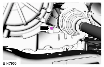
| A6 CHECK THE ENGINE COOLANT FOR TRANSMISSION FLUID | ||||
Is transmission fluid evident in the engine coolant?
|
||||
| A7 CHECK THE TRANSMISSION FLUID FOR ENGINE COOLANT | ||||
Is engine coolant evident in the transmission fluid?
|
||||
| A8 CHECK THE COOLING SYSTEM FOR COMBUSTION GASES | ||||
|
NOTE: Use UView Combustion Leak Tester part number UVU560000-R or equivalent.
Are combustion gases present?
|
The Engine Overheats
Normal operation and Fault Conditions
The engine cooling system maintains the engine temperature during operation. Correct coolant flow through the engine, radiator and remainder of cooling system passages and components is essential to maintaining a correct engine temperature.
Engine coolant flows primarily from the engine to the radiator circuit and back to the coolant pump. Coolant is sent from the coolant pump through the engine block and cylinder heads. A separate circuit from the engine also feeds the heater core with coolant. The coolant pump circulates the coolant. The coolant thermostat is a control valve actuated by coolant temperature. When the thermostat is closed, coolant flow bypasses the radiator circuit and returns to the coolant pump. When the thermostat is opened, coolant flows through the radiator circuit to transfer engine-generated heat to the outside air.
Engine overheating generally occurs when there is a disruption in the ability to control either coolant flow at the correct rate, the inability to transfer heat from the engine through the coolant (including low coolant) or an inability to transfer engine-generated heat to the outside air through the radiator.
Possible Sources
- Active grill shutter
- Low coolant level
- External engine coolant leak
- Airlock in system
- Pressure relief cap installation
- Restricted airflow through A/C condenser/radiator
- Internal engine coolant leak
- Coolant condition/concentration
- Non-OEM engine enhancement components
- Electric cooling fan
- ECT sensor
- Radiator
- Thermostat
- Temperature gauge
- Coolant pump
- Coolant flow restriction
Diagnostic Trouble Code (DTC) Fault Trigger Conditions
| DTC | Description | Fault Trigger Conditions |
| P0217 | Engine Coolant Overtemperature Condition | Sets in the PCM when an engine overheat condition was sensed by the ECT sensor. |
| P1285 | Cylinder Head Overtemperature Condition | Sets in the PCM when an engine overheat condition was sensed by the CHTsensor or the ECT sensor. |
| P1299 | Cylinder Head Overtemperature Protection Active | Sets in the PCM when an engine overheat condition was sensed by the CHT sensor or the ECT sensor. A failure mode effects strategy called fail-safe cooling was activated to cool the engine. |
PINPOINT TEST B : PINPOINT TEST
| B1 CARRY OUT INSPECTION AND VERIFICATION | ||||
Are any concerns present?
|
||||
| B2 CHECK FOR PCM (POWERTRAIN CONTROL MODULE) DTCS | ||||
Is DTC P0217, P1285, or P1299 present?
|
||||
| B3 CHECK THE ACTIVE GRILL SHUTTER OPERATION | ||||
Does the upper and lower grill shutter fully open and close?
|
||||
| B4 CHECK FOR AN AIRFLOW OBSTRUCTION AND MISSING AIR DEFLECTORS | ||||
|
NOTE: Verify no vehicle front end damage is present.
Is an airflow obstruction present or air deflectors missing?
|
||||
| B5 CHECK THE ELECTRIC COOLING FAN OPERATION | ||||
Did the electric cooling fan operate?
|
||||
| B6 PRESSURE TEST THE DEGAS BOTTLE CAP | ||||
Does the cap pass the pressure test?
|
||||
| B7 CHECK THE ENGINE COOLANT LEVEL AND PRESSURE TEST THE ENGINE COOLING SYSTEM | ||||
|
NOTE: Allow the engine to cool before checking the engine coolant level.
Does the pressure maintain 124 - 138 kPa (18 - 20 PSI) for a minimum of 2 minutes?
|
||||
| B8 CHECK THE ENGINE COOLANT FOR AN INTERNAL LEAK | ||||
Is engine oil evident in the coolant?
|
||||
| B9 CHECK THE ENGINE OIL FOR COOLANT | ||||
Is coolant evident in the oil?
|
||||
| B10 CHECK THE ENGINE COOLANT FOR TRANSMISSION FLUID | ||||
Is transmission fluid evident in the engine coolant?
|
||||
| B11 CHECK THE TRANSMISSION FLUID FOR ENGINE COOLANT | ||||
Is engine coolant evident in the transmission fluid?
|
||||
| B12 INSPECT THE CHARGE AIR COOLER | ||||
Are any concerns present?
|
||||
| B13 CHECK THE COOLING SYSTEM FOR COMBUSTION GASES | ||||
|
NOTE: Use UView Combustion Leak Tester part number UVU560000-R or equivalent.
Are combustion gases present?
|
||||
| B14 CHECK THE COOLANT PUMP OPERATION | ||||
Is the heater outlet hose hot?
|
||||
| B15 VISUALLY INSPECT THE THERMOSTAT | ||||
Is the thermostat damaged?
|

The Engine Does Not Reach Normal Operating Temperature
Normal operation and Fault Conditions
The engine cooling system maintains engine temperature during operation. Correct coolant flow through the engine, radiator and remainder of cooling system passages and components is essential to maintaining a correct engine temperature.
Engine coolant flows primarily from the engine to the radiator circuit and back to the coolant pump. Coolant is sent from the coolant pump through the engine block and cylinder heads. A separate circuit from the engine also feeds the heater core with coolant. The coolant pump circulates the coolant. The coolant thermostat is a control valve actuated by coolant temperature. When the thermostat is closed, coolant flow bypasses the radiator circuit and returns to the coolant pump. When the thermostat is opened, coolant flows through the radiator circuit in order to transfer engine generated heat to the outside air.
Concerns of engine inability to reach normal operating temperature typically occur when the rate of coolant flow through some coolant circuits (radiator, heater core) is more than expected given the conditions. Heat is not allowed to build in the engine because a heat exchanger is removing too much heat, including the radiator, heater core and oil cooler. In addition, perceived concerns that the engine does not reach normal operating temperature can be related to a low coolant level or trapped air which does not allow for hot coolant to be available at the heater core, an inoperative climate control system, or for concerns perceived or related to an incorrect engine temperature gauge indication.
Possible Sources
- Low coolant level
- Thermostat
- ECT sensor
- Temperature gauge
Diagnostic Trouble Code (DTC) Fault Trigger Conditions
| DTC | Description | Fault Trigger Conditions |
| P0125 | Insufficient Coolant Temp for Closed Loop Fuel Control | Sets in the PCM when the ECT sensor has not achieved the required temperature level to enter closed loop operating conditions within a specified amount of time after starting the engine. |
| P0128 | Coolant Thermostat (Coolant Temp Below Thermostat Regulating Temperature) | Sets in the PCM when the thermostat monitor has not achieved the required engine operating temperature within a specified amount of time after starting the engine. |
PINPOINT TEST C : PINPOINT TEST
 WARNING:
Always allow the engine to cool before opening the
cooling system. Do not unscrew the coolant pressure relief cap when the
engine is operating or the cooling system is hot. The cooling system is
under pressure; steam and hot liquid can come out forcefully when the
cap is loosened slightly. Failure to follow these instructions may
result in serious personal injury.
WARNING:
Always allow the engine to cool before opening the
cooling system. Do not unscrew the coolant pressure relief cap when the
engine is operating or the cooling system is hot. The cooling system is
under pressure; steam and hot liquid can come out forcefully when the
cap is loosened slightly. Failure to follow these instructions may
result in serious personal injury.
|
||||
| C1 CARRY OUT INSPECTION AND VERIFICATION | ||||
Were any concerns found?
|
||||
| C2 CHECK FOR DTC (DIAGNOSTIC TROUBLE CODE) P0125 OR P0128 | ||||
Is DTC P0125 or P0128 present?
|
||||
| C3 CHECK THE COOLANT LEVEL | ||||
|
NOTE: Allow the engine to cool before checking the coolant expansion tank.
Is the engine coolant level within specification?
|
||||
| C4 CHECK THE ECT (ENGINE COOLANT TEMPERATURE) SENSOR OPERATION | ||||
Is the temperature reading similar to the ECT PID value?
|
Component Tests
Cooling System Pressure Test
 WARNING:
Always allow the engine to cool before opening the
cooling system. Do not unscrew the coolant pressure relief cap when the
engine is operating or the cooling system is hot. The cooling system is
under pressure; steam and hot liquid can come out forcefully when the
cap is loosened slightly. Failure to follow these instructions may
result in serious personal injury.
WARNING:
Always allow the engine to cool before opening the
cooling system. Do not unscrew the coolant pressure relief cap when the
engine is operating or the cooling system is hot. The cooling system is
under pressure; steam and hot liquid can come out forcefully when the
cap is loosened slightly. Failure to follow these instructions may
result in serious personal injury.
NOTE: Vehicles have a pressure relief cap on the degas bottle and no radiator cap.
-
Turn the engine OFF.
-
Check the engine coolant level and adjust as necessary.
-
Remove the degas bottle cap. Inspect the degas bottle
cap and degas bottle for any issues that would cause improper sealing,
such as for cross-threading, burrs, damaged o-ring, etc. If any issues
are found, INSTALL a new cap and/or degas bottle.
-
Attach the Pressure Tester and adaptor (Snap-On TA53 or
equivalent), to the degas bottle cap. The cap must hold pressure of 145
kPa +/- 21 kPa (21 PSI +/- 3 PSI). If any issues are found, INSTALL a
new cap.
-
Attach the Pressure Tester and adaptor (Snap-On TA52,
AST ASSFZ-47, Redline RDL95-0750 or equivalent) to the degas bottle.
NOTICE: Do not pressurize the cooling system beyond the maximum pressure listed in the specifications table in this section, or cooling system components can be damaged.
NOTE: If the plunger of the pressure tester is pressed too fast, an erroneous pressure reading will result.
-
To pressurize the engine cooling system, slowly press
the plunger of the pressure test pump and increase the pressure to
between 124 - 138 kPa (18 - 20 PSI). Observe the gauge reading for
approximately 2 minutes. Pressure should not drop during this time. If
the pressure drops within this time, inspect for leaks and repair as
necessary.
-
Allow the vehicle to sit for a minimum of 5 hours, or overnight.
NOTE: 2-4 psi of pressure drop is normal and expected after engine cool down.
-
If the pressure drops more than the expected range of
2-4 psi and no leaks are found and the pressure drops, the leak may be
internal to the engine. Inspect the coolant for engine oil and the
engine oil for coolant.
REFER to: Engine (303-00 Engine System - General Information, Diagnosis and Testing).
-
If the pressure does not drop remove the cooling system Pressure Tester and adaptor from degas bottle.
-
Install the degas bottle cap until it contacts the hard stop.
Thermostat
Install a new thermostat only after at least one of the following tests and checks have been carried out:
- Pinpoint Test B or C
- Thermostat Visual Inspection
Thermostat Visual Inspection
-
Remove the thermostat.
-
Examine the thermostat for signs of damage including:
- Valve not fully seated (light visible through the valve)
- Foreign material lodged in the main valve
- Bent or broken frame or flange
- Bent or broken spring
- Wax leaking from wax reservoir or a bulge in the reservoir
- Any other damage or distortion
-
NOTE: If no damage is found during the inspection, do not attempt to open the thermostat using hot water or other heat sources. This method is not an accurate means to test the function of the thermostat and may damage the thermostat.
If damage is found during the inspection, remove any foreign material or broken pieces and install a new thermostat.
Radiator Leak Test, Removed From Vehicle
NOTICE: Never leak test an aluminum radiator in the same water that copper/brass radiators are tested in. Flux and caustic cleaners may be present in the cleaning tank and they will damage aluminum radiators.
NOTE: Clean the radiator before leak testing to avoid contamination of tank.
-
Leak test the radiator in clean water with air
pressurized to the maximum pressure listed in the Specifications table.
Charge Air Cooler Radiator Leak Test, Removed From Vehicle
NOTICE: Never leak test an aluminum radiator in the same water that copper/brass radiators are tested in. Flux and caustic cleaners may be present in the cleaning tank and they will damage aluminum radiators.
NOTE: Clean the radiator before leak testing to avoid contamination of tank.
-
Leak test the radiator in clean water with air
pressurized to the maximum pressure listed in the Specifications table.
 Engine Cooling - System Operation and Component Description. Description and Operation
System Operation
Engine coolant flows primarily from the engine to the radiator circuit
and back to the coolant pump. Coolant is sent from the coolant pump
through the engine block and cylinder head...
 Engine Cooling System Draining, Vacuum Filling and Bleeding. General Procedures
Special Tool(s) /
General Equipment
ROB75240Coolant/Battery Refractometer (Fahrenheit)
Fluid Container
Cooling System Vacuum Tester and Refiller
Draining
NOTICE:
The coolant must be recovered in a suitable, clean container
for reuse...
Other information:
Ford Fusion 2013–2020 Service Manual: Transmission Fluid Cooler Tubes - 1.5L EcoBoost (110kW/150PS) – I4. Removal and Installation
Special Tool(s) / General Equipment 307-569Disconnect Tool TOC Line (1/2)TKIT-2006U-F/FMTKIT-2006U-FLM/LMTKIT-2006U-ROW1TKIT-2006U-ROW2 Materials Name Specification Motorcraft® MERCON® LV Automatic Transmission FluidXT-10-QLVC WSS-M2C938-AMERCON® LV, Removal With the vehicle in N, position it on a hoist...
Ford Fusion 2013–2020 Service Manual: Evaporator Inlet and Outlet Manifold. Removal and Installation
Removal NOTICE: During the removal or installation of components, cap, tape or otherwise appropriately protect all openings and tubes/fittings to prevent the ingress of dirt or other contamination. Remove caps, tape and other protective materials prior to installation...
Categories
- Manuals Home
- 2nd Generation Ford Fusion Owners Manual
- 2nd Generation Ford Fusion Service Manual
- Transmission - 1.5L EcoBoost (118kW/160PS) – I4. Removal and Installation
- Pre-Collision Assist (IF EQUIPPED)
- Body Control Module (BCM). Removal and Installation
- New on site
- Most important about car
Using Seatbelts During Pregnancy
WARNING: Always ride and drive with your seatback upright and properly fasten your seatbelt. Fit the lap portion of the seatbelt snugly and low across the hips. Position the shoulder portion of the seatbelt across your chest. Pregnant women must follow this practice. See the following figure.
