Ford Fusion: Engine - 1.5L EcoBoost (118kW/160PS) – I4 / Engine. Assembly
Special Tool(s) / General Equipment
 |
100-002
(TOOL-4201-C)
Holding Fixture with Dial Indicator Gauge |
 |
300-OTC1819E 2,200# Floor Crane, Fold Away |
 |
303-103
(T74P-6375-A)
Holding Tool, Flywheel T74P-77000-A TKIT-2009TC-F |
 |
303-1097 Locking Tool, Variable Camshaft Timing Oil Control Unit TKIT-2010B-FLM TKIT-2010B-ROW |
 |
303-1502 Lifting Device Engine TKIT-2012A-FL TKIT-2012A-ROW |
 |
303-1532 Installer, Camshaft Seal TKIT-2010B-FLM TKIT-2010B-ROW |
 |
303-1550 Alignment Tool, Crankshaft Vibration Damper TKIT-2012A-FL TKIT-2012A-ROW |
 |
303-1552 Alignment Tool, Camshaft TKIT-2012A-FL TKIT-2012A-ROW |
 |
303-1567 Sizer, Teflon Seal TKIT-2010C-FLM |
 |
303-175
(T82L-6316-A)
Installer, Crankshaft Vibration Damper TKIT-1982-F |
 |
303-335
(T88T-6701-A)
Installer, Front Cover Oil Seal TKIT-1988-FLM TKIT-1988-F |
 |
303-393-02 Adapter for 303-393 TKIT-2012A-FL TKIT-2012A-ROW |
 |
303-393A Locking Tool, Flywheel TKIT-2012A-FL TKIT-2012A-ROW |
 |
303-420
(T92P-6701-BH)
Installer, Crankshaft Front Oil Seal TKIT-1992-FLMH/LMH TKIT-1992-LMH/MH |
 |
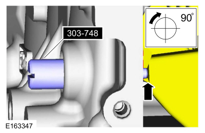
303-748 Locking Tool, Crankshaft TKIT-2010B-FLM TKIT-2010B-ROW |
 |
310-205 Fuel Injector Brush |
 |
310-207 Installer, Fuel Injector Seal Assembly TKIT-2009A-FLM |
| Feeler Gauge | |
| M6 Tap | |
| Hose Clamp Remover/Installer | |
| Piston Ring Compressor | |
Materials
| Name | Specification |
|---|---|
| Motorcraft® Threadlock 262 TA-26 |
WSK-M2G351-A6 |
| Motorcraft® High Performance Engine RTV Silicone TA-357 |
WSE-M4G323-A6 |
| Flange Sealant CU7Z-19B508-A |
WSS-M2G348-A11 |
| Motorcraft® Metal Surface Prep Wipes ZC-31-B |
- |
| Engine Oil - SAE 5W-20 - Synthetic Blend Motor Oil XO-5W20-Q1SP |
WSS-M2C945-B1 |
| Motorcraft® Orange Concentrated Antifreeze/Coolant VC-3-B |
WSS-M97B44-D |
| Flange Sealant - Anaerobic Loctite® 51031 |
WSK-M2G348-A7 |
| Motorcraft® Metal Brake Parts Cleaner PM-4-A, PM-4-B |
- |
NOTICE: During engine repair procedures, cleanliness is extremely important. Any foreign material, including any material created while cleaning gasket surfaces that enters the oil passages, coolant passages or the oil pan, can cause engine failure.
NOTE: Refer to exploded views in Description and Operation.
-
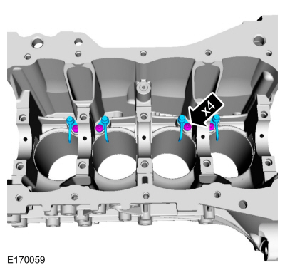
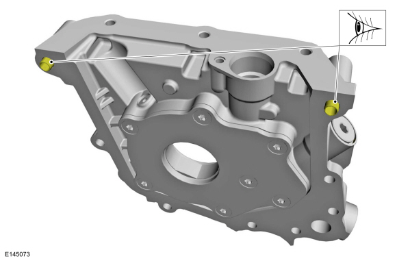
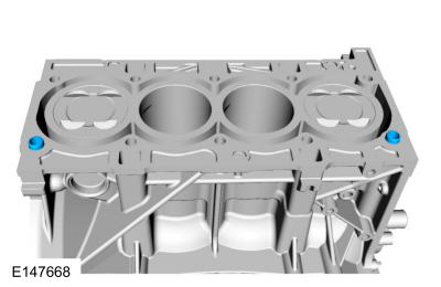
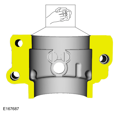
Install the engine piston oil cooler valves and the bolts.
Torque: 80 lb.in (9 Nm)
 |
-
-
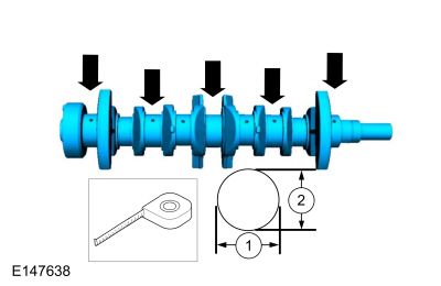
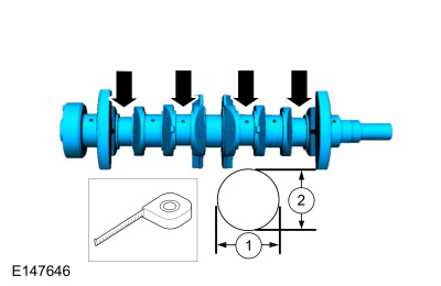
Measure the length in two directions.
-
Record the smallest measurement for each crankshaft main bearing journal.
-
Measure the length in two directions.
 |
-
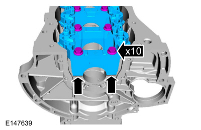
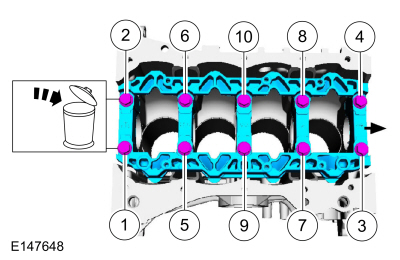
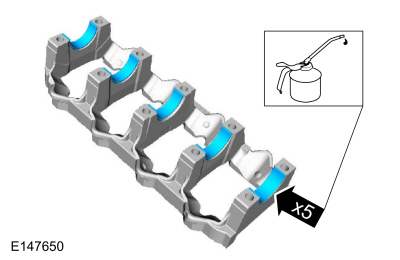
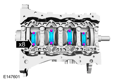
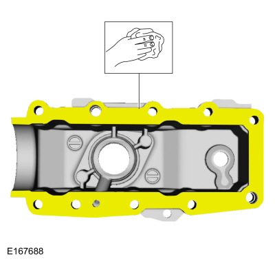
NOTE: Mounted flush and finger tight.
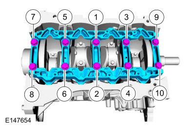
Mount the main bearing beam flush with the block and install the bolts finger-tight.
 |
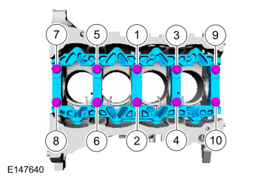
-
Tighten the main bearing beam bolts in sequence shown in 4 stages.
Torque:
Stage 1: 22 lb.ft (30 Nm)
Stage 2: 37 lb.ft (50 Nm)
Stage 3: 45°
Stage 4: 45°
 |
-
Measure the length in five places.
 |
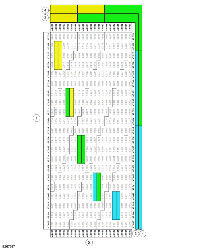
-
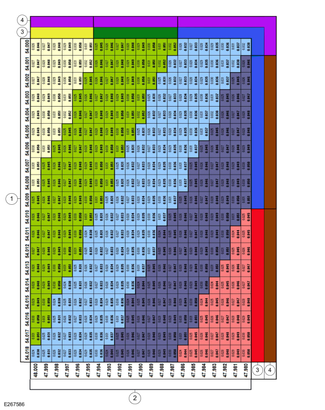
Using the chart, select the correct grade main bearings.
-
Cylinder block bore diameter
-
Crankshaft journal diameter
-
Upper bearing color code
-
Lower bearing color code
-
Cylinder block bore diameter
 |
-
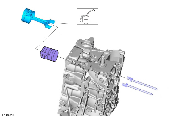
NOTICE: The rod cap installation must keep the same orientation as marked during disassembly or engine damage may occur.
NOTE: Use the original connecting rod cap bolts.
Using the original bolts, install the connecting rod caps and the bolts in 3 stages.
Torque:
Stage 1: 159 lb.in (18 Nm)
Stage 2: 45°
Stage 3: 45°
 |
-
-
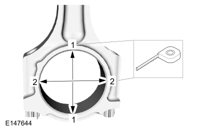
Measure the length or distance in two directions.
-
Record the smallest measurement for each connecting rod.
-
Measure the length or distance in two directions.
 |
-
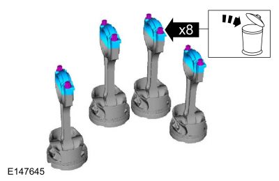
Remove the bolts and the connecting rod caps. Discard the bolts.
 |
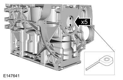
-
-
Measure the length in two directions.
-
Record the smallest measurement for each connecting rod journal.
-
Measure the length in two directions.
 |
-
Using the chart, select the correct grade connecting rod bearings for each crankshaft connecting rod journal.
-
Connecting rod bore diameter
-
Crankshaft connecting rod journal diameter
-
Upper bearing color code
-
Lower bearing color code
-
Connecting rod bore diameter
 |
-
Remove the bolts and the main bearing beam. Discard the bolts.
 |
-
NOTE: Before assembling the cylinder block, all sealing surfaces must be free of chips, dirt, paint and foreign material. Also, make sure the coolant and oil passages are clear.
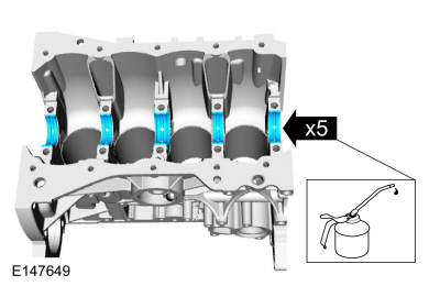
NOTE: If reusing the crankshaft main bearings, install them in their original positions and orientation as noted during disassembly.
Lubricate with clean engine oil and install crankshaft main bearings.
Material: Engine Oil - SAE 5W-20 - Synthetic Blend Motor Oil / XO-5W20-Q1SP (WSS-M2C945-B1)
 |
-
NOTE: If reusing the crankshaft main bearings, install them in their original positions and orientation as noted during disassembly.
Lubricate with clean engine oil and install the main beam bearings.
Material: Engine Oil - SAE 5W-20 - Synthetic Blend Motor Oil / XO-5W20-Q1SP (WSS-M2C945-B1)
 |
-
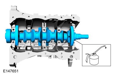
Lubricate with clean engine oil and install the crankshaft.
Material: Engine Oil - SAE 5W-20 - Synthetic Blend Motor Oil / XO-5W20-Q1SP (WSS-M2C945-B1)
 |
-
Lubricate with clean engine oil and install the main beam bearings.
Material: Engine Oil - SAE 5W-20 - Synthetic Blend Motor Oil / XO-5W20-Q1SP (WSS-M2C945-B1)
 |
- Mounted flush.
 |
-
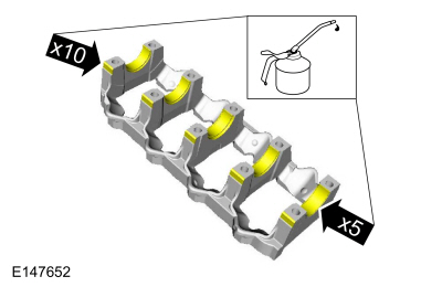
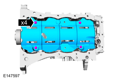
NOTE: Lubricate the main bearing beam bolts threads with clean engine oil.
Install the main bearings beam and the bolts and tighten the bolts in sequence shown in 4 stages.
Material: Engine Oil - SAE 5W-20 - Synthetic Blend Motor Oil / XO-5W20-Q1SP (WSS-M2C945-B1)
Torque:
Stage 1: 22 lb.ft (30 Nm)
Stage 2: 37 lb.ft (50 Nm)
Stage 3: 45°
Stage 4: 45°
 |
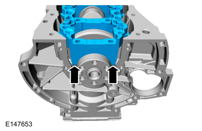
-
-
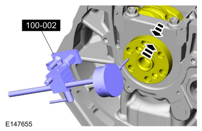
Position the crankshaft to the rear of the cylinder block.
-
Zero the Dial Indicator Gauge with Holding Fixture.
Use Special Service Tool: 100-002 (TOOL-4201-C) Holding Fixture with Dial Indicator Gauge.
-
Move the crankshaft to the front of the cylinder block. Note and record the crankshaft end play.
-
Acceptable crankshaft end play is 0.12-0.43 mm
(0.008-0.017 in). If the crankshaft end play exceeds the specified
range, install new parts as necessary.
-
Position the crankshaft to the rear of the cylinder block.
 |
-
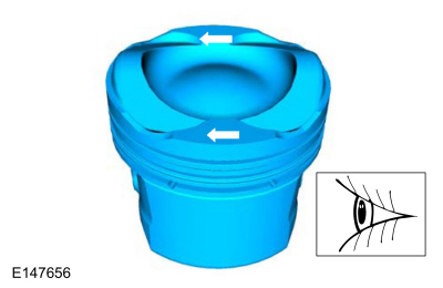
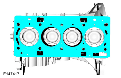
Arrows faces the front of the engine.
 |
-
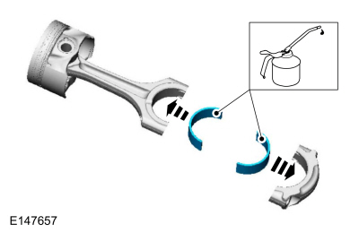
NOTE: If reusing the connecting rod bearings, install them in their original positions and orientation as noted during disassembly.
Lubricate with clean engine oil and install the connecting rod bearings.
Material: Engine Oil - SAE 5W-20 - Synthetic Blend Motor Oil / XO-5W20-Q1SP (WSS-M2C945-B1)
 |
-
NOTE: The upper and lower compression rings are to be fitted with the identification marks on the upper side.
NOTE: Arrows faces the front of the engine.
-
Upper compression ring gap location.
-
Lower compression ring gap location.
-
Upper oil control segment ring gap location.
-
Expander ring gap location.
-
Lower oil control segment ring gap location.
-
Upper compression ring gap location.
 |
-
NOTE: Using a connecting rod installer will unsure not to scratch the cylinder wall or crankshaft journal with the connecting rod. Push the piston down until the connecting rod bearing seats on the crankshaft journal.
NOTE: Make sure the piston arrows on top is facing toward the front of the engine.
Using the Piston ring Compressor, lubricate with clean engine oil and install the pistons.
Use the General Equipment: Piston Ring Compressor
Material: Engine Oil - SAE 5W-20 - Synthetic Blend Motor Oil / XO-5W20-Q1SP (WSS-M2C945-B1)
 |
-
NOTICE: The rod cap installation must keep the same orientation as marked during disassembly or engine damage may occur.
NOTE: After installation of each connecting rod cap, rotate the crankshaft to verify smooth operation.
NOTE: Use new connecting rod caps bolts.
Install connecting rod caps and bolts on the connecting rods for cylinders 1 and 4 first and tighten. Then rotate crankshaft 180 degrees and install connecting rod caps and bolts on connecting rods for cylinders 2 and 3 and tighten.
Torque:
Stage 1: 159 lb.in (18 Nm)
Stage 2: 45°
Stage 3: 45°
 |
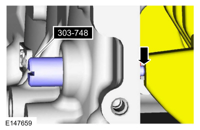
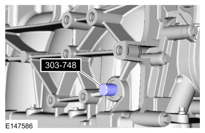
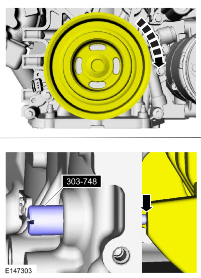
- Install Special Service Tool: 303-748 Locking Tool, Crankshaft.
 |
-
NOTE: Only rotate the crankshaft clockwise direction.
Rotate the crankshaft slowly clockwise until the crankshaft balance weight is up against the crankshaft locking tool. The engine is now at TDC.
 |
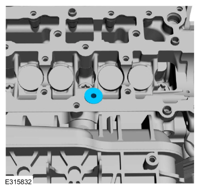
-
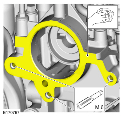
Install the new oil pump gasket.
 |
-
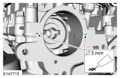
NOTE: Make sure that the locating dowels remain installed.
Inspect the oil pump locating dowels for damage and correct installation.
 |
-
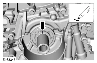
Prime the oil pump. Add 2 tablespoons of clean engine oil to the oil pump and rotate the oil pump by hand.
-
NOTE: Only tighten the bolts finger tight at this stage.
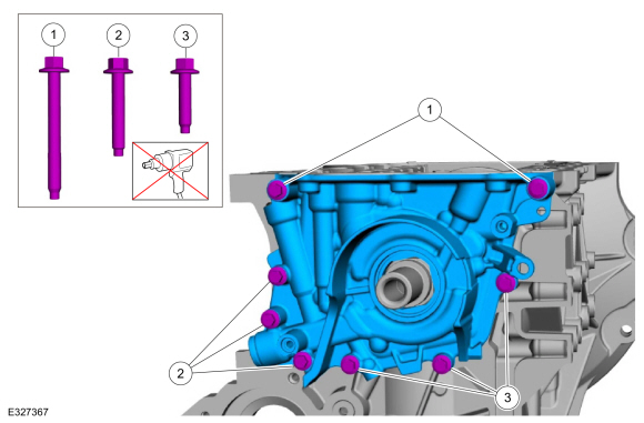
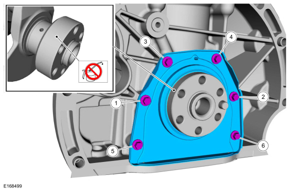
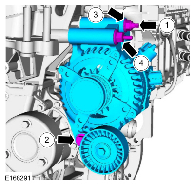
Install the oil pump and follow the steps below. Hand start the bolts.
-
Install the two M6 x 55 mm bolts finger tight.
-
Install the three M6 x 35 mm bolts finger tight.
-
Install the three M6 x 25 mm bolts finger tight.
-
Install the two M6 x 55 mm bolts finger tight.
 |
-
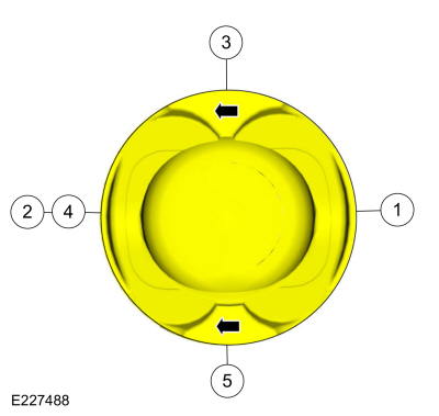
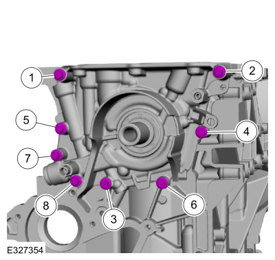
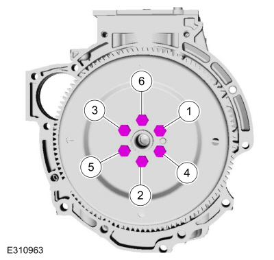
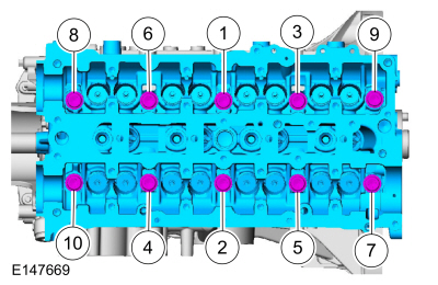
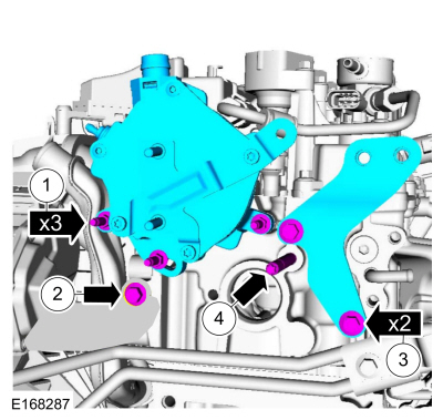
Tighten the oil pump bolts in sequence shown in 2 stages.
Torque:
Stage 1: Tighten bolts 1, 2, 3 and 6: 18 lb.in (2 Nm)
Stage 2: Tighten bolts 1 through 8: 97 lb.in (11 Nm)
 |
-
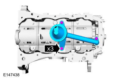
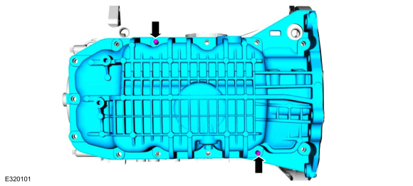
Install the oil pan baffle and the bolts.
Torque: 84 lb.in (9.5 Nm)
 |
-
NOTE: New crankshaft rear seal is supplied with an alignment sleeve which must be removed after installation.
NOTE: Do not remove the alignment sleeve from the crankshaft rear seal prior to installation on the crankshaft.
Align the crankshaft rear seal and alignment sleeve on the crankshaft and push the crankshaft rear seal off the alignment sleeve onto the crankshaft without stopping until the crankshaft rear seal meets the cylinder block.
Torque:
Stage 1: 35 lb.in (4 Nm)
Stage 2: 89 lb.in (10 Nm)
 |
-
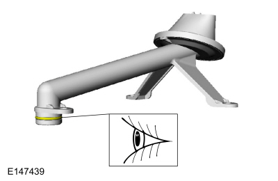
NOTE: The O-ring seal is to be reused unless damaged.
Inspect the oil pump screen and pickup tube O-ring seal.
 |
-
Install the oil pump screen and pickup tube and the bolts.
Torque: 84 lb.in (9.5 Nm)
 |
-
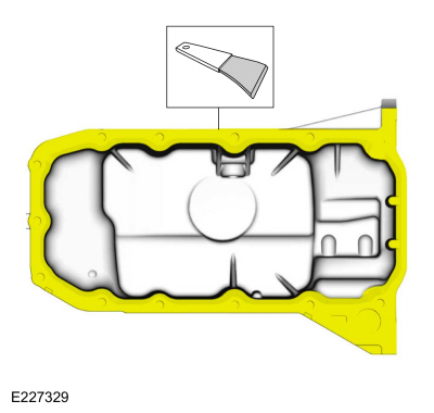
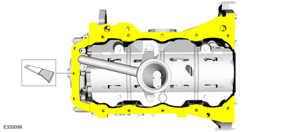
Clean and prepare the RTV sealing surface.
Refer to: RTV Sealing Surface Cleaning and Preparation (303-00 Engine System - General Information, General Procedures).
 |
-
Clean and prepare the RTV sealing surface.
Refer to: RTV Sealing Surface Cleaning and Preparation (303-00 Engine System - General Information, General Procedures).
 |
-
Clean and prepare the RTV sealing surface.
Refer to: RTV Sealing Surface Cleaning and Preparation (303-00 Engine System - General Information, General Procedures).
 |
-
Install the following items:
-
NOTE: The use of the two studs will aid on the alignment of the oil pan.
Two M8x20 studs.
-
 |
-
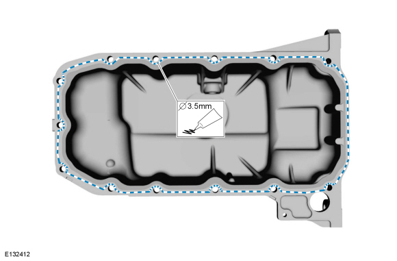
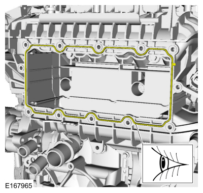
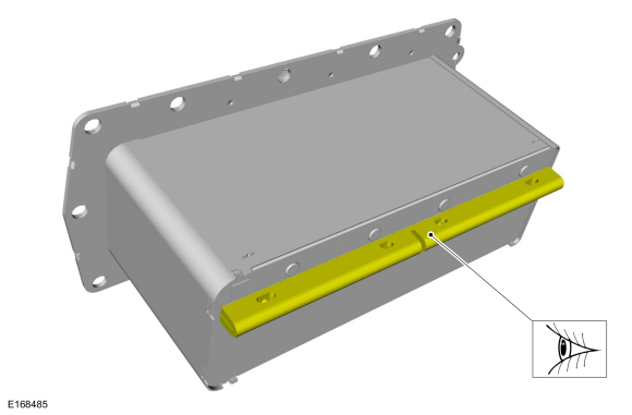
NOTE: The component must be installed within 5 minutes of applying the sealant.
Apply a 3.5 mm (0.137 in) bead of silicone sealant.
Material: Motorcraft® High Performance Engine RTV Silicone / TA-357 (WSE-M4G323-A6)
 |
-
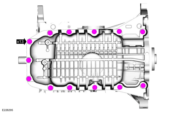
Install the oil pan and remove the two M8x20 studs.
 |
-
NOTE: Using a straight edge, align the back of the oil pan to the cylinder block.
Install the oil pan bolts finger tight.
 |
-
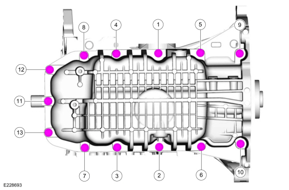
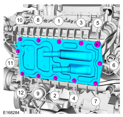
Tighten the bolts in sequence shown.
Torque: 168 lb.in (19 Nm)
 |
-
Install the flexplate and the bolts finger-tight.
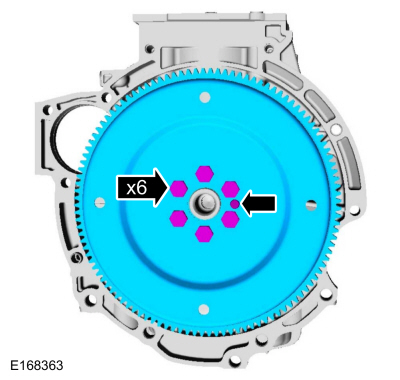 |
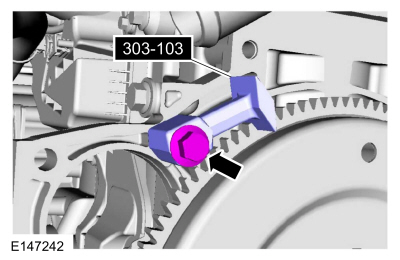
- Install Special Service Tool: 303-103 (T74P-6375-A) Holding Tool, Flywheel.
 |
-
Tighten the flexplate bolts in sequence shown in 4 stages.
Torque:
Stage 1: 133 lb.in (15 Nm)
Stage 2: 18 lb.ft (25 Nm)
Stage 3: 22 lb.ft (30 Nm)
Stage 4: 90°
 |
- Remove Special Service Tool: 303-103 (T74P-6375-A) Holding Tool, Flywheel.
 |
-
NOTE: Only rotate the crankshaft clockwise direction.
Verify the crankshaft balance weight is up against the crankshaft locking tool.
 |
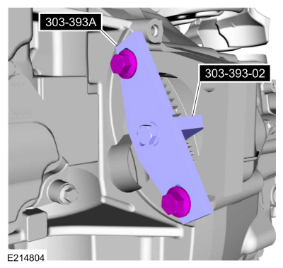
- Install Special Service Tool: 303-393-02 Adapter for 303-393. , 303-393A Locking Tool, Flywheel.
 |
-
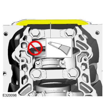
NOTICE: Do not use metal scrapers, wire brushes, power abrasive discs or other abrasive means to clean the sealing surfaces. These tools cause scratches and gouges that make leak paths. Use a plastic scraping tool to remove all traces of the head gasket.
NOTE: If there is no residual gasket material present, metal surface prep can be used to clean and prepare the surfaces.
Make sure that the mating faces are clean and free of foreign material.
Material: Motorcraft® Metal Surface Prep Wipes / ZC-31-B
 |
-
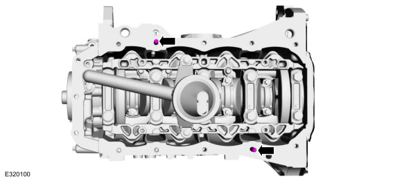
Install the dowels.
 |
-
Install the new cylinder head gasket.
 |
-
NOTE: The cylinder head bolts are torque-to-yield and must not be reused. New cylinder head bolts must be installed.
NOTE: Make sure that no fluids are present in the cylinder head bolt threaded bores.
Install the cylinder head and the bolts finger-tight and then tighten the bolts in sequence shown in 5 stages.
Torque:
Stage 1: 44 lb.in (5 Nm)
Stage 2: 133 lb.in (15 Nm)
Stage 3: 26 lb.ft (35 Nm)
Stage 4: 90°
Stage 5: 90°
 |
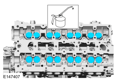
-
Lubricate with clean engine oil and install the valve tappets.
Material: Engine Oil - SAE 5W-20 - Synthetic Blend Motor Oil / XO-5W20-Q1SP (WSS-M2C945-B1)
 |
-
NOTICE: If any new parts are being installed (cylinder head, valves, tappets, camshafts) it is necessary to check the valve clearance, follow the next 12 steps exactly or serious damage to the engine may occur. If the original parts are being installed it is not necessary to check the valve clearance so proceed to step 65.
Place a paint mark on the crankshaft at the 12 o'clock position.
 |
- Remove Special Service Tool: 303-393A Locking Tool, Flywheel. , 303-393-02 Adapter for 303-393.
 |
- Remove Special Service Tool: 303-748 Locking Tool, Crankshaft.
 |
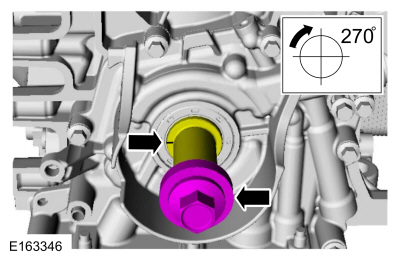
-
NOTE: Rotating the crankshaft will position all of the pistons below the deck of the cylinder block and allow the camshafts to be installed and the valve clearance checked without the possibility of damage to the valves or pistons.
Using the crankshaft bolt and washer, rotate the crankshaft clockwise 270 degrees until the paint mark is at the 9 o'clock position.
 |
-
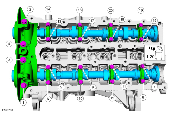
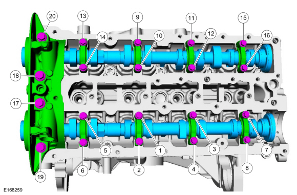
NOTICE: Failure to follow the camshaft tightening procedure can result in damage to the camshafts.
NOTICE: Make sure that the camshafts and camshaft bearing caps are installed in their original locations or damage to the engine may occur.
NOTE: Make sure that the mating faces are clean and free of foreign material.
NOTE: Apply clean engine oil to the bearing surfaces of the camshafts, camshaft bearing caps and the VCT bridge.
Tighten the bolts evenly, half a turn at a time, until the camshaft bearing caps and the VCT bridge are seated against the cylinder head.
Material: Engine Oil - SAE 5W-20 - Synthetic Blend Motor Oil / XO-5W20-Q1SP (WSS-M2C945-B1)
Torque:
Stage 1: Tighten bolts 1 through 16 to: 62 lb.in (7 Nm)
Stage 2: Tighten bolts 17 through 20 to: 89 lb.in (10 Nm)
Stage 3: Tighten bolts 1 through 16 an additional: 45°
Stage 4: Tighten bolts 17 and 18 an additional: 70°
Stage 5: Tighten bolts 19 and 20 an additional: 53°
 |
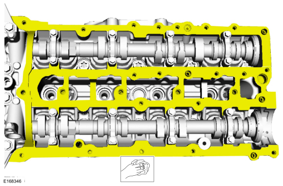
-
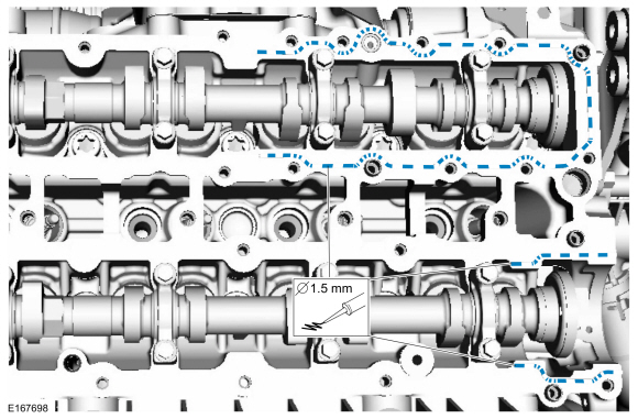
-
Using the flats of the camshaft, rotate the camshaft to
place the cam lobe at base circle, with the lobe pointed away from the
tappet.
-
Use a feeler gauge to measure the clearance of each valve and record its location.
Use the General Equipment: Feeler Gauge
-
Repeat to measure all of the lobe/tappet clearances.
-
Using the flats of the camshaft, rotate the camshaft to
place the cam lobe at base circle, with the lobe pointed away from the
tappet.
 |
-
NOTE: Select tappets using this formula: ideal tappet thickness = measured clearance + the existing tappet thickness - nominal clearance. Select the closest tappet size to the ideal tappet thickness available and mark the installation location.
NOTE: The nominal clearance is 0.0112 in ( .285 mm) for intake and 0.0167 in ( .425 mm) for exhaust.
NOTE: The acceptable clearances after being fully installed is 0.009 –0.013 in ( .24 –.33 mm) for intake and 0.015 –0.019 in ( .38 –.47 mm) for exhaust.
-
NOTICE: Failure to follow the camshaft loosening procedure can result in damage to the camshafts.
NOTE: Note the location and orientation of each camshaft bearing cap and the position of the camshaft lobes on the No. 1 cylinder for installation reference.
Loosen the camshaft bearing caps in sequence 2 turns at a time until all tension is released from the camshaft bearing caps in sequence shown.
 |
- Install Special Service Tool: 303-748 Locking Tool, Crankshaft.
 |
-
NOTE: Rotating the crankshaft will position the engine at TDC and allow you to install the camshafts in the same position as noted during the disassembly.
Rotate the crankshaft clockwise 90 degrees so the crankshaft contacts the Timing Peg, Crankshaft TDC 303-748.
 |
-
If necessary, replace any tappets with the correct tappets selected during the valve clearance check.
Material: Engine Oil - SAE 5W-20 - Synthetic Blend Motor Oil / XO-5W20-Q1SP (WSS-M2C945-B1)
 |
-
NOTE: Verify the crankshaft contacts the Timing Peg and the engine is still at TDC.
Install Special Service Tool: 303-393A Locking Tool, Flywheel. , 303-393-02 Adapter for 303-393.
 |
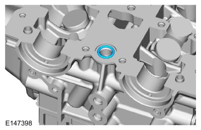
-
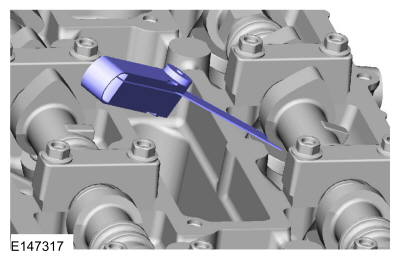
Install a new O-ring seal.
 |
-
Install the crankcase vent oil drain tube.
 |
-
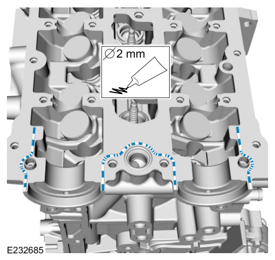
NOTE: The VCT bridge must be installed within 5 minutes of applying the gasket maker.
Apply a 2.0 mm bead of flange sealant.
Material: Flange Sealant / CU7Z-19B508-A (WSS-M2G348-A11)
 |
-
NOTICE: Failure to follow the camshaft tightening procedure can result in damage to the camshafts.
NOTICE: Make sure that the camshafts and camshaft bearing caps are installed in their original locations or damage to the engine may occur.
NOTE: Make sure that new bolts are installed.
Tighten the bolts evenly, half a turn at a time, until the camshaft bearing caps and the VCT bridge are seated against the cylinder head.
Torque:
Stage 1: Tighten bolts 1 through 16 to: 62 lb.in (7 Nm)
Stage 2: Tighten bolts 17 through 20 to: 89 lb.in (10 Nm)
Stage 3: Tighten bolts 1 through 16 an additional: 45°
Stage 4: Tighten bolts 17 and 18 an additional: 70°
Stage 5: Tighten bolts 19 and 20 an additional: 53°
 |
-
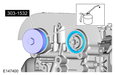
Using the special tool, lubricate with clean engine oil and install the camshaft seals.
Use Special Service Tool: 303-1532 Installer, Camshaft Seal.
Material: Engine Oil - SAE 5W-20 - Synthetic Blend Motor Oil / XO-5W20-Q1SP (WSS-M2C945-B1)
 |
-
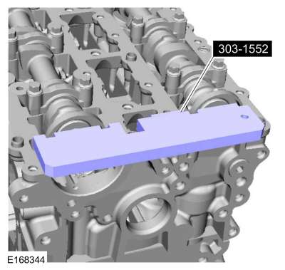
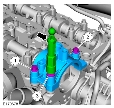
NOTE: It may be necessary to use an open-ended wrench to turn the camshafts by the hexagon to align the camshafts.
Install Special Service Tool: 303-1552 Alignment Tool, Camshaft.
 |
-
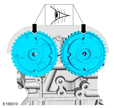
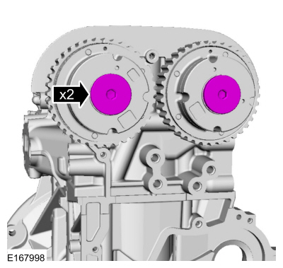
Install the VCT units at the 12 o'clock position.
 |
-
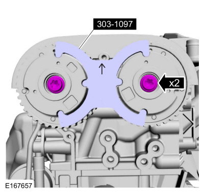
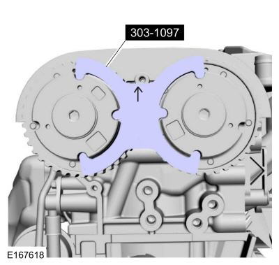
NOTE: The timing mark of each VCT unit must be at the 12 o'clock position.
NOTE: Use an open-ended wrench to hold the camshafts by the hexagon to prevent the camshafts from turning.
Install the VCT units new bolts.
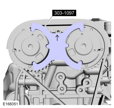
Install Special Service Tool: 303-1097 Locking Tool, Variable Camshaft Timing Oil Control Unit.
Torque: 18 lb.ft (25 Nm)
 |
- Remove Special Service Tool: 303-1097 Locking Tool, Variable Camshaft Timing Oil Control Unit.
 |
- Remove Special Service Tool: 303-1552 Alignment Tool, Camshaft.
 |
-
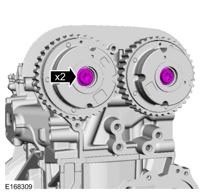
NOTE: Use an open-ended wrench to hold the camshafts by the hexagon to prevent the camshafts from turning.
Tighten an additional:
Torque: 75°
 |
-
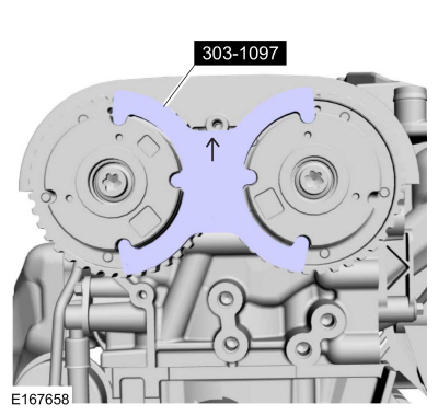
NOTE: The special tool can only be installed if the valve timing is correct.
Install Special Service Tool: 303-1552 Alignment Tool, Camshaft.
 |
-
NOTE: The timing mark of each VCT unit must be at the 12 o'clock position.
NOTE: If the VCT unit bolts are removed again, they must be replaced.
If the special tools cannot be installed, repeat the adjustment according to the preceding steps.
Install Special Service Tool: 303-1097 Locking Tool, Variable Camshaft Timing Oil Control Unit.
 |
- Remove Special Service Tool: 303-1097 Locking Tool, Variable Camshaft Timing Oil Control Unit.
 |
- Remove Special Service Tool: 303-1552 Alignment Tool, Camshaft.
 |
-
NOTE: Use an open-ended wrench to hold the camshafts by the hexagon to prevent the camshafts from turning.
Install the VCT unit caps.
Torque: 142 lb.in (16 Nm)
 |
-
NOTE: The timing mark of each VCT unit must be at the 12 o'clock position.
Install Special Service Tool: 303-1097 Locking Tool, Variable Camshaft Timing Oil Control Unit.
 |
-
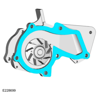
Install the new coolant pump gasket.
 |
-
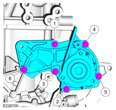
Install the coolant pump and the new bolts and tighten in sequence shown in 2 stages.
Torque:
Stage 1: 53 lb.in (6 Nm)
Stage 2: 89 lb.in (10 Nm)
 |
-
Install the timing belt tensioner and the bolt. WARNING:
The timing belt tensioner spring is under load. Extra
care must be taken at all times when handling the tensioner. Failure to
follow this instruction may result in personal injury.
WARNING:
The timing belt tensioner spring is under load. Extra
care must be taken at all times when handling the tensioner. Failure to
follow this instruction may result in personal injury.
Torque: 18 lb.ft (25 Nm)
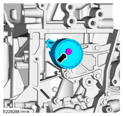 |
-
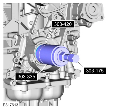
With clean engine oil, lubricate the lip of the crankshaft front seal.
 |
-
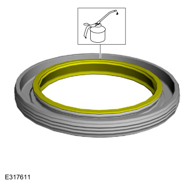
NOTE: Make sure that the mating faces are clean and free of foreign material.
NOTE: Click here to view a video version of installing the crankshaft front seal.
View - English

With the seal slightly angled, carefully place the seal lip against the crankshaft sealing surface. Apply lateral pressure and "walk" the seal lip around the remaining circumference.
 |
-
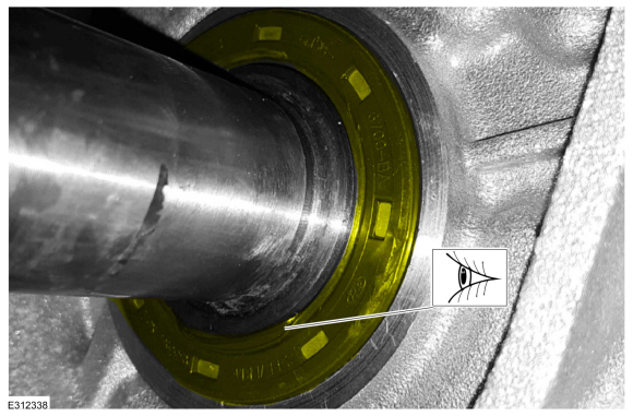
-
Inspect the crankshaft front seal.
-
NOTICE: If the crankshaft front seal is rolled during positioning, do not use the special tool to install or an oil leak will occur.
If any part of the crankshaft front seal inner lip is rolled, remove and reposition the seal. Also make sure the seal spring is properly positioned on the seal.
-
Inspect the crankshaft front seal.
 |
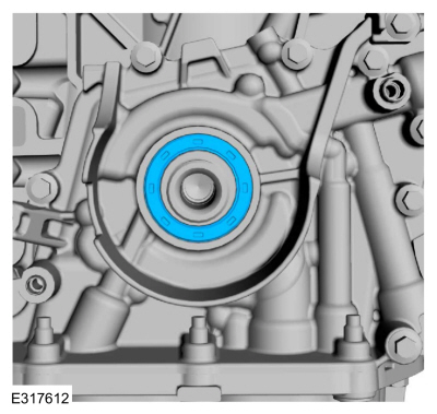
-
Using the special tools, seat the new crankshaft front seal.
Use Special Service Tool: 303-175 (T82L-6316-A) Installer, Crankshaft Vibration Damper. , 303-335 (T88T-6701-A) Installer, Front Cover Oil Seal. , 303-420 (T92P-6701-BH) Installer, Crankshaft Front Oil Seal.
 |
-
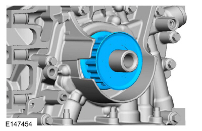
NOTE: Before installation, clean and inspect the sprocket for any damage. If damage is evident, replace the sprocket. If no damage, the sprocket is to be reused.
Install the timing belt sprocket.
 |
-
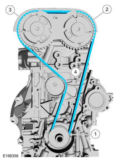
NOTE: Install the timing belt in the following sequence.
Install the timing belt in the following sequence.
 |
-
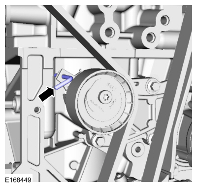
Remove the holding pin. WARNING:
The timing belt tensioner spring is under load. Extra
care must be taken at all times when handling the tensioner. Failure to
follow this instruction may result in personal injury.
WARNING:
The timing belt tensioner spring is under load. Extra
care must be taken at all times when handling the tensioner. Failure to
follow this instruction may result in personal injury.
 |
-
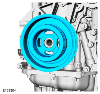
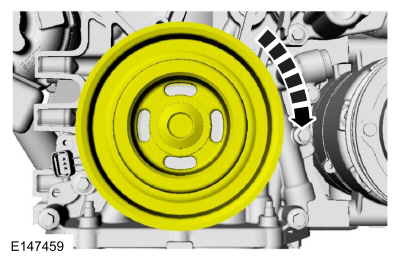
Install the crankshaft pulley.
 |
-
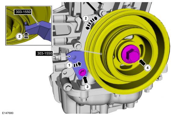
- Install Special Service Tool: 303-1550 Alignment Tool, Crankshaft Vibration Damper.
-
Rotate crankshaft pulley to align the Special Tool:
Use Special Service Tool: 303-1550 Alignment Tool, Crankshaft Vibration Damper.
-
Finger tight at this stage.
-
Using a new bolt, finger tight at this stage.
 |
-
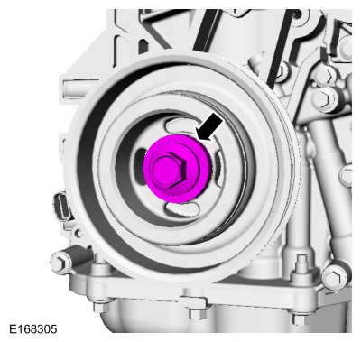
NOTE: Make certain the special tools that secure the flywheel from rotating are still installed prior to performing this step. Failure to secure the flywheel may cause misalignment of the crankshaft pulley to the crankshaft resulting in driveability concerns.
Tighten the crankshaft pulley bolt in 4 stages.
Torque:
Stage 1: 74 lb.ft (100 Nm)
Stage 2: 90°
Stage 3: Wait 2 s
Stage 4: 15°
 |
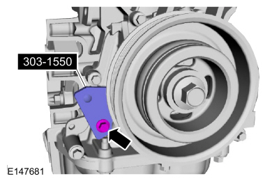
- Remove Special Service Tool: 303-1550 Alignment Tool, Crankshaft Vibration Damper.
 |
- Remove Special Service Tool: 303-748 Locking Tool, Crankshaft.
 |
- Remove Special Service Tool: 303-1097 Locking Tool, Variable Camshaft Timing Oil Control Unit.
 |
- Remove Special Service Tool: 303-393-02 Adapter for 303-393. , 303-393A Locking Tool, Flywheel.
 |
-
NOTE: Only rotate the crankshaft in a clockwise direction.
Rotate about 1 3/4 turns.
 |
- Install Special Service Tool: 303-748 Locking Tool, Crankshaft.
 |
-
NOTE: Only rotate the crankshaft in a clockwise direction.
Rotate the crankshaft slowly clockwise until the crankshaft balance weight is up against the crankshaft locking tool. The engine is now at TDC.
 |
-
NOTE: The timing mark of each VCT unit must be at the 12 o'clock position.
NOTE: It may necessary to rotate the camshafts slightly to install the special tool.
If the special tool cannot be installed, repeat the adjustment according to the preceding steps.
Install Special Service Tool: 303-1097 Locking Tool, Variable Camshaft Timing Oil Control Unit.
 |
- Remove Special Service Tool: 303-1097 Locking Tool, Variable Camshaft Timing Oil Control Unit.
 |
- Remove Special Service Tool: 303-748 Locking Tool, Crankshaft.
 |
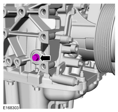
-
Install the engine plug bolt.
Torque: 177 lb.in (20 Nm)
 |
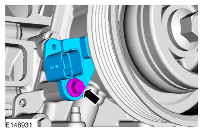
-
Install the CKP sensor and the bolt.
Torque: 89 lb.in (10 Nm)
 |
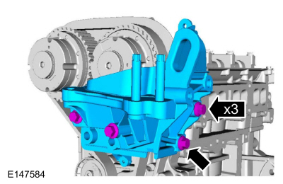
-
NOTE: There are different length of bolts noted in disassembly.
Install the engine mount bracket and the bolts.
Torque: 41 lb.ft (55 Nm)
 |
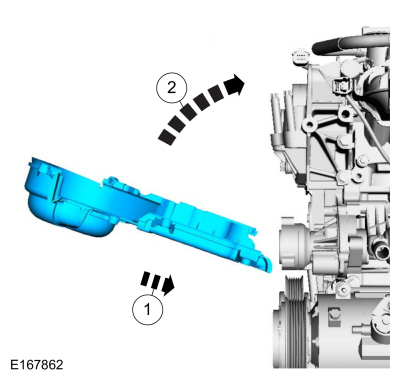
-
Install the engine front cover.
 |
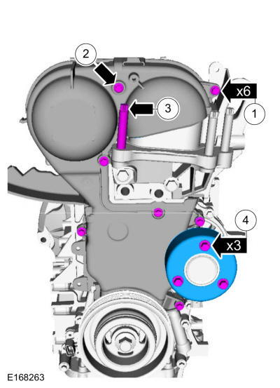
-
-
Install the engine front cover bolts.
Torque: 89 lb.in (10 Nm)
-
Install the engine front cover bolt.
Torque: 89 lb.in (10 Nm)
-
Install the engine mount stud finger-tight.
-
Install the coolant pump pulley and the bolts.
Torque: 18 lb.ft (24 Nm)
-
Install the engine front cover bolts.
 |
-
Install the cover to engine front cover and install the stud bolt.
Torque: 89 lb.in (10 Nm)
 |
-
If equipped, install the block heater and the nut.
Torque: 27 lb.in (3 Nm)
 |
-
Install the TC mounting studs and the gasket.
Torque: 89 lb.in (10 Nm)
 |
-
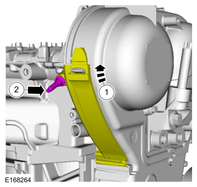
NOTICE: Do-not use a metal brush; damage to sealing area will result in leaks.
-
Carefully use a nylon brush to remove the old O-ring
residue and use brake cleaner to rinse the O-ring residue out of the
turbocharger O-ring bore. Inspect the area for deep scratches and
gouges.
-
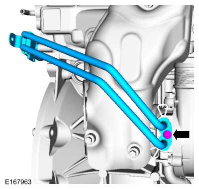
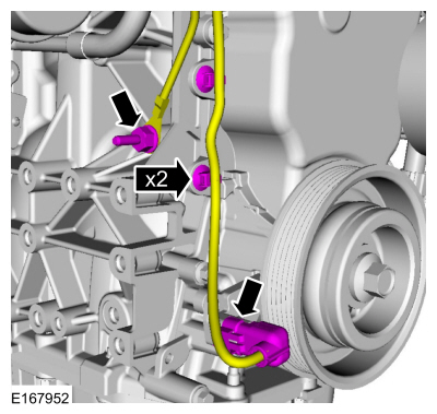
Install the new TC oil
supply tube assembly, including the new bolt, the new sealing washers
and the new O-ring seals. Lubricate the new O-ring seals with clean
engine oil.
Material: Motorcraft® Metal Brake Parts Cleaner / PM-4-A, PM-4-B
Torque: 19 lb.ft (26 Nm)
-
Carefully use a nylon brush to remove the old O-ring
residue and use brake cleaner to rinse the O-ring residue out of the
turbocharger O-ring bore. Inspect the area for deep scratches and
gouges.
 |
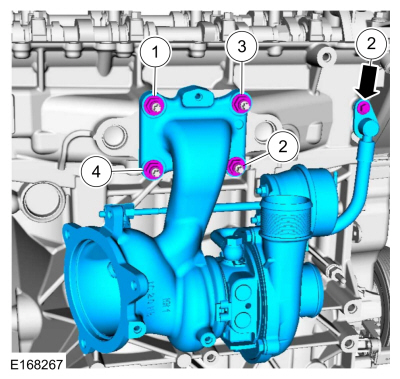
-
-
Tighten in the sequence as shown.
Install the TC and the nuts in sequence shown in 3 stages.
Torque:
Stage 1: 62 lb.in (7 Nm)
Stage 2: 124 lb.in (14 Nm)
Stage 3: 17 lb.ft (23 Nm)
-
Install the TC oil supply tube retainer.
Torque: 89 lb.in (10 Nm)
-
Tighten in the sequence as shown.
 |
-
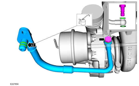
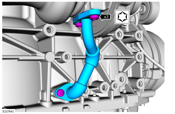
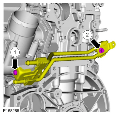
Install the new TC oil return tube gasket. Lubricate the O-ring seal with clean engine oil.
Material: Engine Oil - SAE 5W-20 - Synthetic Blend Motor Oil / XO-5W20-Q1SP (WSS-M2C945-B1)
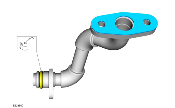 |
-
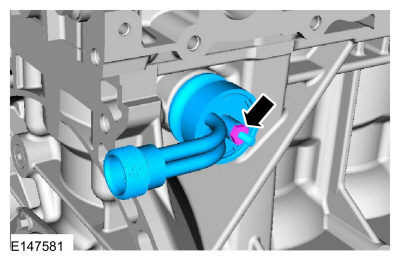
NOTICE: Do-not use a metal brush; damage to sealing area will result in leaks.
-
Carefully use a nylon brush to remove the old O-ring
residue and use brake cleaner to rinse the O-ring residue out of the
turbocharger tube to engine O-ring bore. Inspect the area for deep
scratches and gouges.
-
Install the new turbocharger oil return tube, then install and tighten the turbocharger oil return tube bolts.
Material: Motorcraft® Metal Brake Parts Cleaner / PM-4-A, PM-4-B
Torque: 89 lb.in (10 Nm)
-
Carefully use a nylon brush to remove the old O-ring
residue and use brake cleaner to rinse the O-ring residue out of the
turbocharger tube to engine O-ring bore. Inspect the area for deep
scratches and gouges.
 |
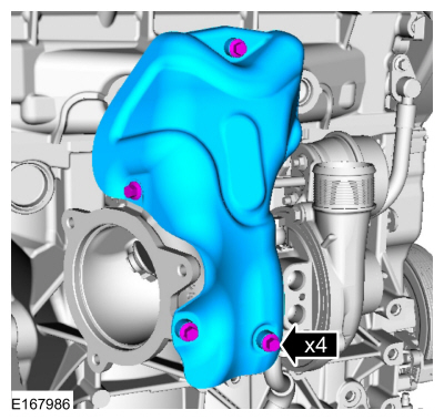
-
Install the TC heat shield and the bolts.
Torque: 89 lb.in (10 Nm)
 |
-
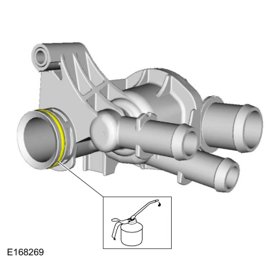
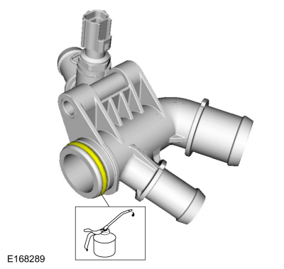
Lubricate the thermostat housing O-ring seal.
Material: Motorcraft® Orange Concentrated Antifreeze/Coolant / VC-3-B (WSS-M97B44-D)
 |
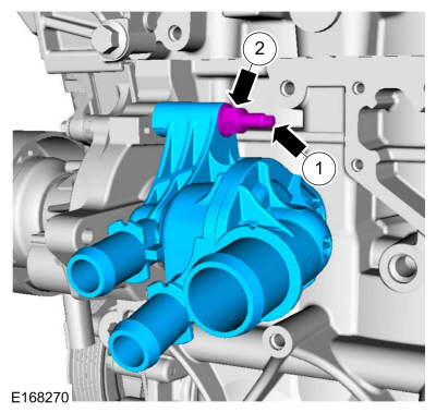
-
-
Install the thermostat housing and the stud.
Torque: 44 lb.in (5 Nm)
-
Install the thermostat housing nut.
Torque: 150 lb.in (17 Nm)
-
Install the thermostat housing and the stud.
 |
-
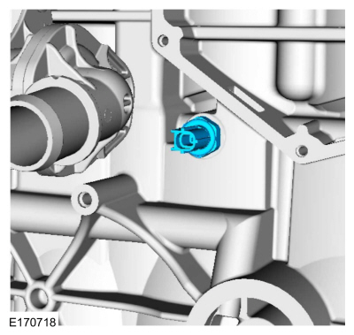
Install the new oil pressure switch.
Torque: 159 lb.in (18 Nm)
 |
-
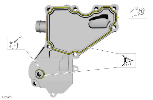
NOTE: Lubricate the spigot with clean engine oil.
Inspect the crankcase vent oil separator gasket. Lubricate the crankcase vent oil separator O-ring seal.
Material: Engine Oil - SAE 5W-20 - Synthetic Blend Motor Oil / XO-5W20-Q1SP (WSS-M2C945-B1)
 |
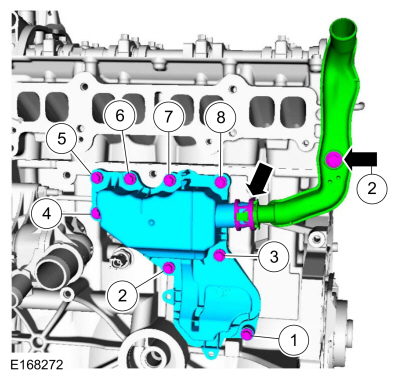
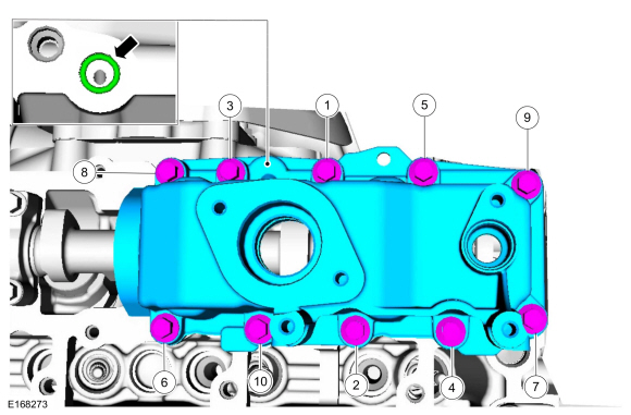
-
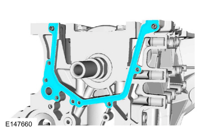
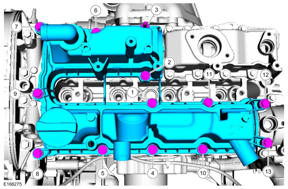
-
Install the crankcase vent oil separator and the bolts in sequence shown in 3 stages.
Torque:
Stage 1: Torque bolts 1, 2 and 3 to: 49 lb.in (5.5 Nm)
Stage 2: Torque bolts 4, 5, 6, 7 and 8 to: 49 lb.in (5.5 Nm)
Stage 3: Torque all bolts in sequence to: 84 lb.in (9.5 Nm)
-
Install the crankcase vent oil separator inlet pipe and the bolt.
Torque: 35 lb.in (4 Nm)
-
Install the crankcase vent oil separator and the bolts in sequence shown in 3 stages.
 |
-
NOTE: The head of the KS should not touch any other component.
NOTE: The LH KS must be at the 10 o'clock position and the RH KS must be at the 2 o'clock position.
Install the KS, bolts and attach the retainer.
Torque: 159 lb.in (18 Nm)
 |
-
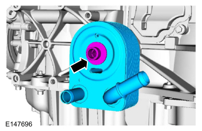
NOTICE: A new oil cooler must be installed or severe damage to the engine can occur.
Install the new oil cooler and the retainer.
Torque: 41 lb.ft (55 Nm)
 |
-
NOTICE: Do not use metal scrapers, wire brushes, power abrasive discs or other abrasive means to clean the sealing surfaces. These tools cause scratches and gouges which make leak paths.
Make sure that the mating faces are clean and free of foreign material.
Material: Motorcraft® Metal Surface Prep Wipes / ZC-31-B
 |
-
NOTICE: Do not use metal scrapers, wire brushes, power abrasive discs or other abrasive means to clean the sealing surfaces. These tools cause scratches and gouges which make leak paths.
Make sure that the mating faces are clean and free of foreign material.
Material: Motorcraft® Metal Surface Prep Wipes / ZC-31-B
 |
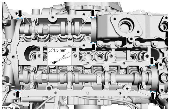
-
NOTE: The components must be installed within 5 minutes of applying the sealant.
Apply a 1.5 mm (0.059 in) bead of sealant.
Material: Flange Sealant / CU7Z-19B508-A (WSS-M2G348-A11)
 |
-
-
Install the brake vacuum pump cap, bolts and the stud bolt in sequence shown in 2 stages.
Torque:
Stage 1: 35 lb.in (4 Nm)
Stage 2: 89 lb.in (10 Nm)
-
Install the engine cover mounting stud.
Torque: 44 lb.in (5 Nm)
-
Install the brake vacuum pump cap, bolts and the stud bolt in sequence shown in 2 stages.
 |
-
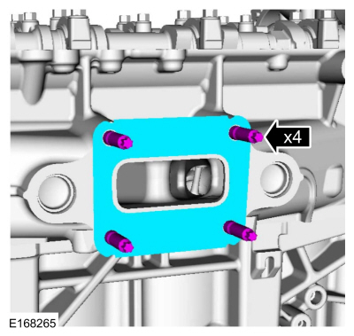
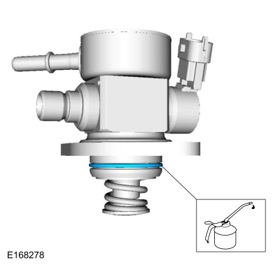
NOTE: Use a new O-ring seal.
Install the a new O-ring seal, high-pressure fuel pump drive unit and the bolts and tighten in sequence shown in 3 stages.
Torque:
Stage 1: Tighten bolts 1 through 8 to: 35 lb.in (4 Nm)
Stage 2: Tighten bolts 1 through 8 to: 124 lb.in (14 Nm)
Stage 3: Tighten bolts 9 and 10 to: 97 lb.in (11 Nm)
 |
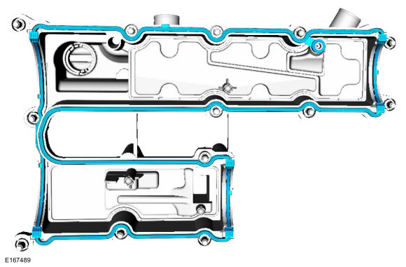
-
Install the new valve cover gasket.
 |
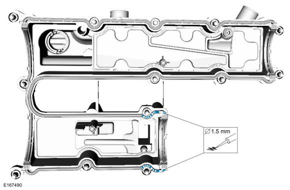
-
NOTE: The components must be installed within 5 minutes of applying the sealant.
Apply a 1.5 mm (0.059 in) bead of sealant.
Material: Flange Sealant / CU7Z-19B508-A (WSS-M2G348-A11)
 |
-
Apply a 1.5 mm (0.059 in) bead of sealant.
Material: Flange Sealant / CU7Z-19B508-A (WSS-M2G348-A11)
 |
-
Install the valve cover and the bolts finger-tight and then tighten the bolts in sequence shown in 3 stages.
Torque:
Stage 1: 44 lb.in (5 Nm)
Stage 2: 80 lb.in (9 Nm)
Stage 3: 89 lb.in (10 Nm)
 |
-
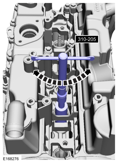
NOTE: A clean working environment is essential to prevent dirt or foreign material contamination.
NOTE: Make sure to thoroughly clean any residual fuel or foreign material from the cylinder head, block and the general surrounding area of the fuel rails and injectors.
NOTE: Do not use compressed air to clean the tip of the fuel injector.
NOTE: Do not use a brush to clean the tip of the fuel injector.
Clean the fuel injector bores.
Use Special Service Tool: 310-205 Fuel Injector Brush.
 |
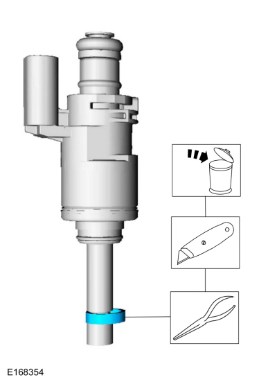
-
Remove and discard the fuel injector O-ring seal and washer.
 |
-
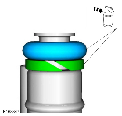
NOTICE: Use care when removing the lower Teflon® seals, not to scratch, nick or gouge the fuel injectors.
NOTICE: Do not attempt to cut the lower Teflon® seal without first pulling it away from the fuel injector or damage to the injector may occur.
-
Pull the lower Teflon® seal away from the injector.
-
Carefully cut and discard the lower fuel injector Teflon® seals.
-
Pull the lower Teflon® seal away from the injector.
 |
-
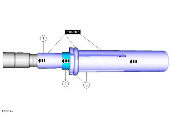
NOTICE: Do not lubricate the new lower Teflon® fuel injector seals.
- Use Special Service Tool: 310-207 Installer, Fuel Injector Seal Assembly.
-
NOTICE: Once the Teflon® seal is installed on the Teflon® Seal Guide, it should immediately be installed onto the fuel injector to avoid excessive expansion of the Teflon® seal.
NOTE: Make sure that new lower fuel injector Teflon® seals are installed.
-
Using the Pusher Tool, slide the Teflon® seals off of
the Teflon® Seal Guide and into the groove on the fuel injectors.
Use Special Service Tool: 310-207 Installer, Fuel Injector Seal Assembly.
 |
-
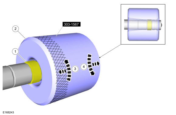
NOTICE: Install the fuel injectors into the cylinder head within 15 minutes of sizing the seals due to Teflon® seal expansion.
NOTE: Make sure the Teflon® seal is fully seated in the groove on the fuel injector before sizing the Teflon® seal.
-
Some Teflon® seal massaging with your fingers before the
Teflon® seal sizer tool is installed will aid in installing the Teflon®
seal sizer tool.
-
Position the Teflon® seal sizer tool with the larger
opening towards the Teflon® seal. Push while turning the Teflon® seal
sizer tool 180 degrees.
Use Special Service Tool: 303-1567 Sizer, Teflon Seal.
-
Once the Teflon® seal sizer tool is installed, check and
make sure the Teflon® seal is in the sizing portion of the Teflon® seal
sizer tool. After one minute, turn the Teflon® seal sizer tool back 180
degrees and remove.
-
Some Teflon® seal massaging with your fingers before the
Teflon® seal sizer tool is installed will aid in installing the Teflon®
seal sizer tool.
 |
-
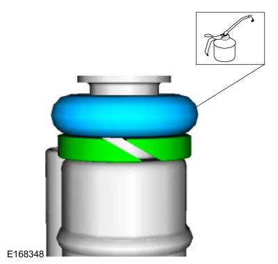
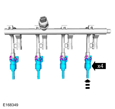
NOTICE: Use fuel injector O-ring seals that are made of special fuel-resistant material. The use of ordinary O-ring seals may cause the fuel system to leak. Do not reuse the O-ring seals.
NOTE: Do not lubricate the new lower Teflon® fuel injector seals.
Lubricate and install the fuel injector O-ring seal and the washer.
Material: Engine Oil - SAE 5W-20 - Synthetic Blend Motor Oil / XO-5W20-Q1SP (WSS-M2C945-B1)
 |
-
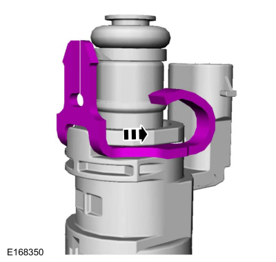
Install the fuel injector clip.
 |
-
NOTE: The anti-rotation finger of the fuel injector clip must slip into the groove of the fuel rail cup.
NOTE: The fuel rail pressure sensor must be replaced if it is removed from the fuel rail.
Install the fuel injectors.
 |
-
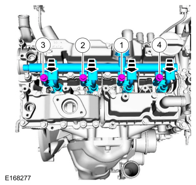
NOTE: Do not lubricate the new lower Teflon® fuel injector seals.
NOTE: Take extra care when handling the components.
NOTE: Only tighten the 4 fuel rail bolts finger tight at this stage.
Apply a force of 90 lb (400 N) to 224.81 lb (1,000 N) on the fuel rail assembly uniformly above the coil mounting brackets in a direction parallel to the axis of the injectors. This will engage all 4 injector combustion seals into the cylinder head allowing the injectors to seat.
Torque: 17 lb.ft (23 Nm)
 |
-
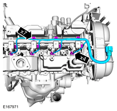
Install the wiring harness and connect the fuel injector electrical connectors and attach the retainers.
 |
-
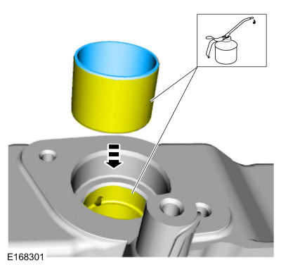
NOTE: The cam lobe for the fuel injection pump must be at BDC for the fuel injection pump installation.
Lubricate and install the high-pressure fuel pump tappet.
Material: Engine Oil - SAE 5W-20 - Synthetic Blend Motor Oil / XO-5W20-Q1SP (WSS-M2C945-B1)
 |
-
Lubricate with clean engine oil and install a new high-pressure fuel pump O-ring seal.
Material: Engine Oil - SAE 5W-20 - Synthetic Blend Motor Oil / XO-5W20-Q1SP (WSS-M2C945-B1)
 |
-
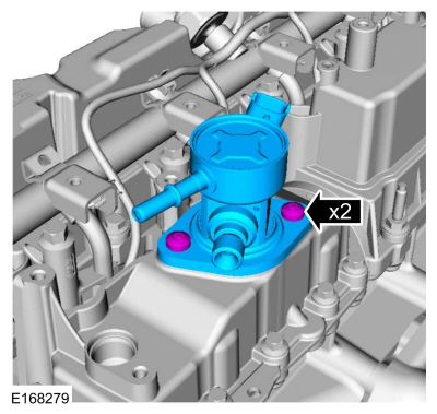
NOTE: Make sure that 2 new fuel injection pump mounting bolts are installed.
NOTE: Install all the bolts finger tight before final tightening.
Install the fuel injection pump and loosely install the 2 fuel injection pump bolts, alternately tighten each bolt one half of a revolution until seated.
Torque: 80 lb.in (9 Nm)
 |
-
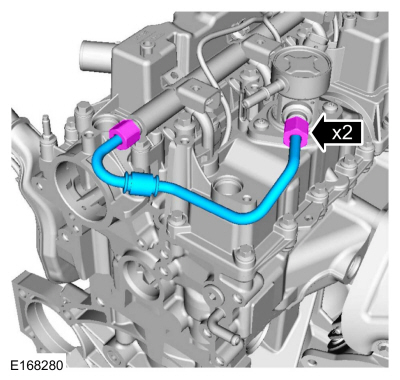
NOTE: Make sure that a new component is installed.
NOTE: Calculate the correct torque wrench setting for the following torque. Refer to Torque Wrench Adapter Formulas.
Install the high-pressure fuel tube and tighten the flare nuts in 3 stages.
Torque:
Stage 1: 15 lb.ft (21 Nm)
Stage 2: Wait 5 min
Stage 3: 15 lb.ft (21 Nm)
 |
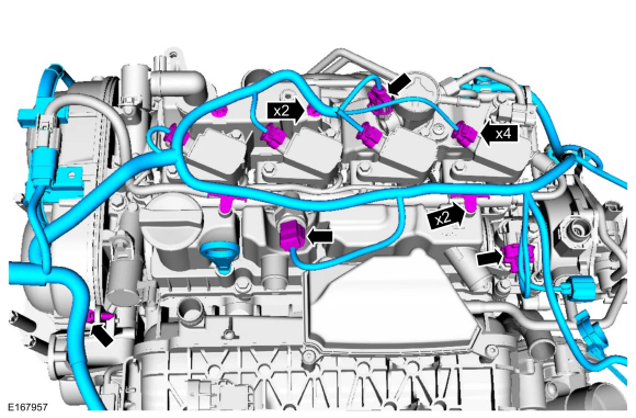
-
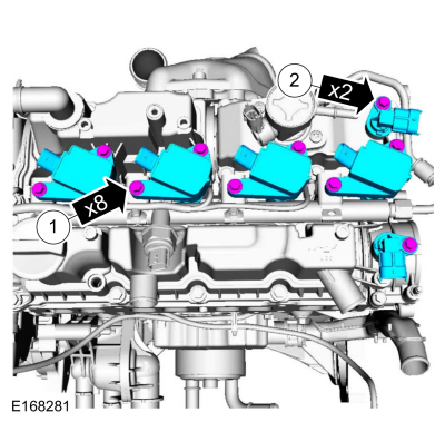
-
Install the ignition coil-on-plugs and the bolts.
Torque: 89 lb.in (10 Nm)
-
Install the CMP sensors and the bolts.
Torque: 80 lb.in (9 Nm)
-
Install the ignition coil-on-plugs and the bolts.
 |
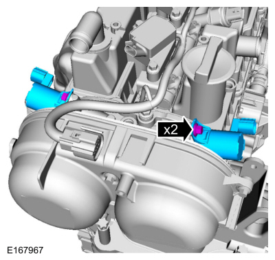
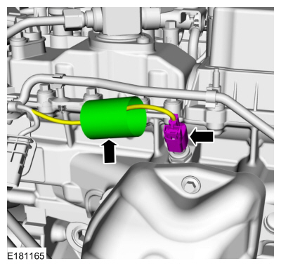
-
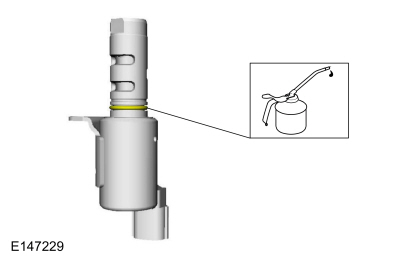
NOTE: The O-ring seals are to be reused unless damaged.
Lubricate the VCT oil control solenoid O-ring seal.
Material: Engine Oil - SAE 5W-20 - Synthetic Blend Motor Oil / XO-5W20-Q1SP (WSS-M2C945-B1)
 |
-
Install the VCT solenoids and the bolts.
Torque: 71 lb.in (8 Nm)
 |
-
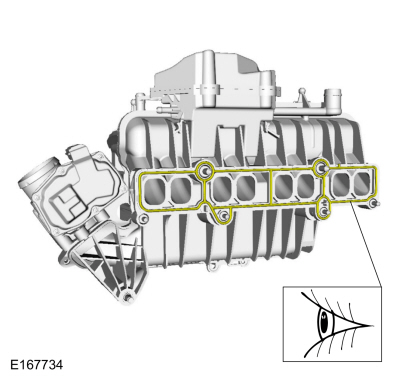
NOTE: Visually inspect the intake manifold gaskets for nicks, cuts and abrasions. If these conditions are not present, the gaskets may be re-used.
Inspect the intake manifold gaskets.
 |
-
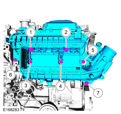
NOTE: Apply threadlock 262 to the intake manifold bolt threads.
NOTE: Make sure the KS wiring connectors are properly routed and not trapped behind the intake manifold while installing the intake manifold.
Install the intake manifold and tighten the bolts in sequence shown.
Material: Motorcraft® Threadlock 262 / TA-26 (WSK-M2G351-A6)
Torque:
Stage 1: Tighten bolts 1, 2 and 7 to: 18 lb.in (2 Nm)
Stage 2: Tighten bolts 3 and 4 to: 18 lb.in (2 Nm)
Stage 3: Tighten bolts 1 and 2 to: 159 lb.in (18 Nm)
Stage 4: Tighten bolts 3, 4, 5 and 6 to: 89 lb.in (10 Nm)
Stage 5: Retighten bolts 1 and 2 to: 159 lb.in (18 Nm)
Stage 6: Tighten bolt 7 to: 159 lb.in (18 Nm)
Stage 7: Retighten bolts 3, 4, 5 and 6 to: 89 lb.in (10 Nm)
 |
-
Inspect the CAC gasket.
 |
-
Inspect the CAC seal.
 |
-
Install the CAC and the bolts in sequence shown in 4 stages.
Torque:
Stage 1: Tighten bolts 7 and 10 to: 18 lb.in (2 Nm)
Stage 2: Hand start remaining bolts: 3 turn(s)
Stage 3: Tighten bolts 1 throught 12 to: 89 lb.in (10 Nm)
Stage 4: Retighten bolts 1 throught 12 to: 89 lb.in (10 Nm)
 |
-
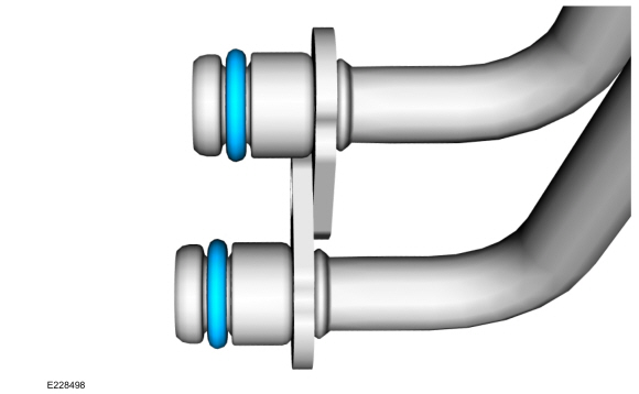
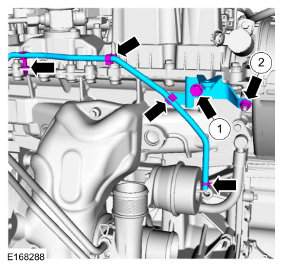
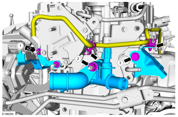
Install the new the turbocharger coolant tube O-ring seals and lubricate with clean engine coolant.
 |
-
Install the TC coolant tube and the retainer.
Torque: 89 lb.in (10 Nm)
 |
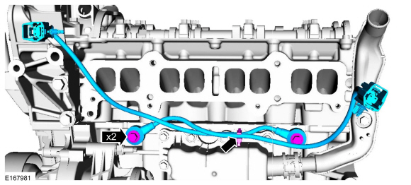
-
-
Position the TC coolant tube and install the retainers.
Torque: 97 lb.in (11 Nm)
- Torque: 17 lb.ft (23 Nm)
-
Position the TC coolant tube and install the retainers.
 |
-
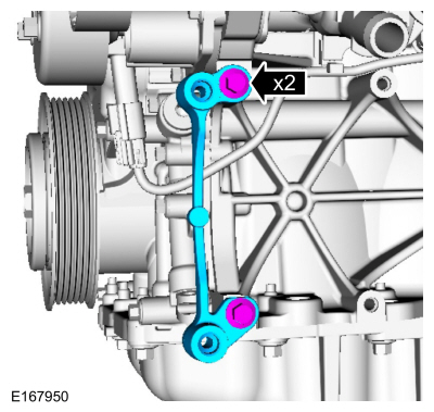
-
Install the bracket and the bolt.
Torque: 17 lb.ft (23 Nm)
-
Install the nut.
Torque: 62 lb.in (7 Nm)
-
Install the TC wastegate control hose and attach the retainers.
-
Install the bracket and the bolt.
 |
-
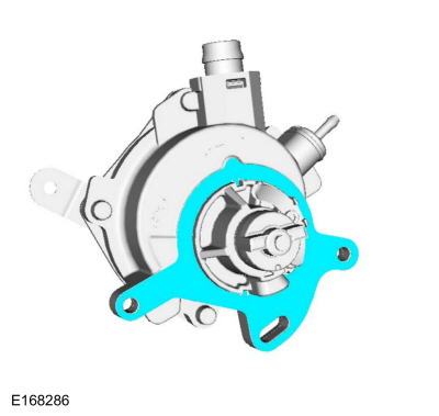
Install the new vacuum pump gasket.
 |
-
NOTE: Make sure the mating surfaces are clean and free of foreign material and the thread lock residue is cleaned from stud bolt holes.
Make sure the mating surfaces are clean and free of foreign material and tap on the vacuum pump mounting hole.
Use the General Equipment: M6 Tap
 |
-
Apply a 3 mm (0.118 in) bead of flange sealant.
Material: Flange Sealant - Anaerobic / Loctite® 51031 (WSK-M2G348-A7)
 |
-
NOTE: Manually align the brake vacuum pump drive key with the camshaft slot before installation.
NOTE: Install new stud bolts for brake vacuum pump.
-
Install the vacuum pump and the new stud bolts.
Torque: 89 lb.in (10 Nm)
-
Install the intake manifold support bracket bolt.
Torque: 159 lb.in (18 Nm)
-
Install the engine lifting bracket and the bolts.
Torque: 168 lb.in (19 Nm)
-
Install the stud.
Torque: 44 lb.in (5 Nm)
-
Install the vacuum pump and the new stud bolts.
 |
-
Lubricate the coolant outlet O-ring seal.
Material: Motorcraft® Orange Concentrated Antifreeze/Coolant / VC-3-B (WSS-M97B44-D)
 |
-
-
Install the bracket and the nuts.
Torque: 62 lb.in (7 Nm)
-
Install the coolant outlet and the nut.
Torque: 159 lb.in (18 Nm)
-
Install the bracket and the bolt.
Torque: 17 lb.ft (23 Nm)
-
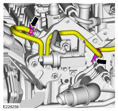
Attach the vacuum hose retainers.
-
Install the bracket and the nuts.
 |
-
Connect the vacuum hose and retainer.
 |
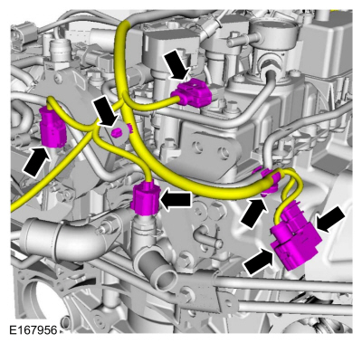
-
-
Install the wiring harness, connect the electrical connectors and attach the retainers.
-
Install the oil level indicator.
-
Install the wiring harness, connect the electrical connectors and attach the retainers.
 |
-
Connect the CHT sensor wiring harness electrical connector and position the cover.
 |
-
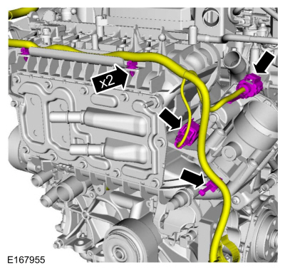
Attach the wiring harness retainers and connect the electrical connectors.
 |
-
Attach the wiring harness retainers and connect the electrical connectors.
 |
-
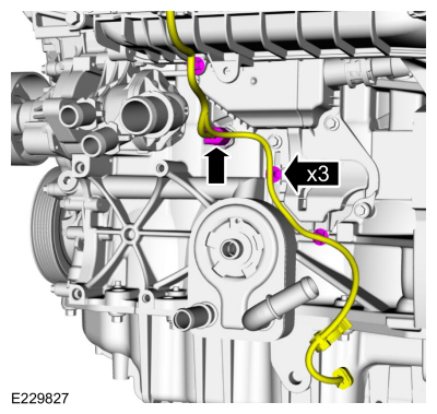
Attach the wiring harness retainers and connect the electrical connector.
 |
-
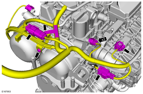
-
Position the wiring harness and connect the electrical connectors.
-
Attach the wiring harness retainer and install the retainer.
Torque: 89 lb.in (10 Nm)
-
Position the wiring harness and connect the electrical connectors.
 |
-
-
Attach the retainers and connect the CKP electrical connector.
-
Position ground cable and install the stud bolt.
Torque: 168 lb.in (19 Nm)
-
Attach the retainers and connect the CKP electrical connector.
 |
-
-
Install the generator and the mounting stud.
Torque: 89 lb.in (10 Nm)
-
Install the generator mounting bolt.
Torque: 35 lb.ft (48 Nm)
-
Install the generator mounting nut.
Torque: 35 lb.ft (48 Nm)
-
Install the generator mounting stud bolt.
Torque: 35 lb.ft (48 Nm)
-
Install the generator and the mounting stud.
 |
-
Install the A/C compressor bracket and the bolts.
Torque: 18 lb.ft (25 Nm)
 |
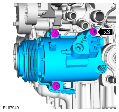
-
Install the A/C compressor and the stud bolts.
Torque: 18 lb.ft (25 Nm)
 |
-
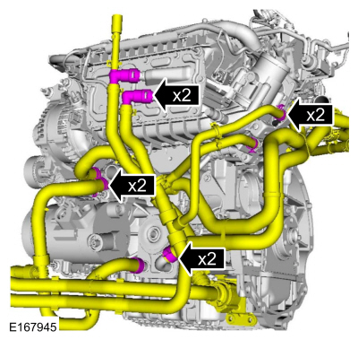
Install the hoses and connect the couplings.
Use the General Equipment: Hose Clamp Remover/Installer
 |
-
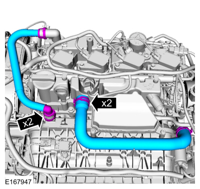
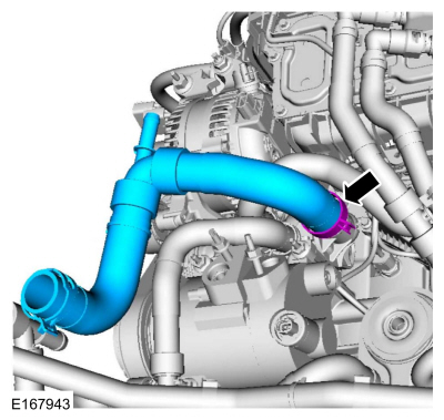
Install and connect the coolant hoses.
Use the General Equipment: Hose Clamp Remover/Installer
 |
-
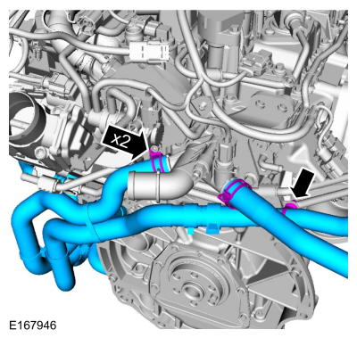
Connect the coolant hoses.
Use the General Equipment: Hose Clamp Remover/Installer
 |
-
Attach the wiring harness retainer and connect the electrical connector.
 |
-
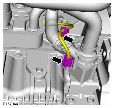
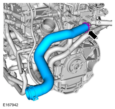
Install and connect the coolant hose.
Use the General Equipment: Hose Clamp Remover/Installer
 |
-
Install and connect the coolant hose.
Use the General Equipment: Hose Clamp Remover/Installer
 |
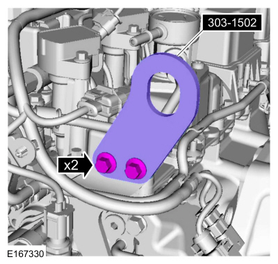
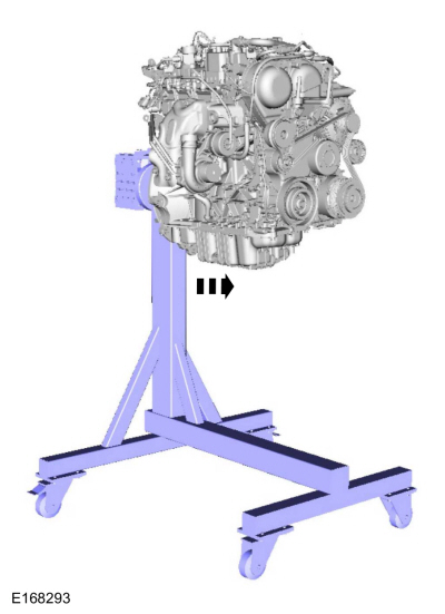
- Install Special Service Tool: 303-1502 Lifting Device Engine.
 |
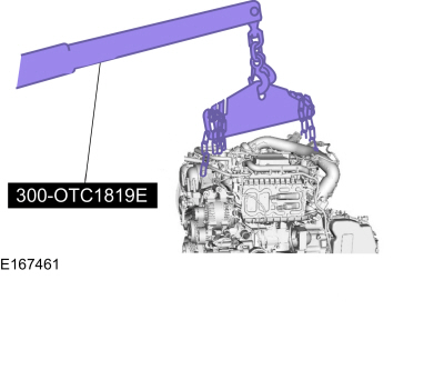
-
Install the floor crane and the special tool.
Install Special Service Tool: 300-OTC1819E 2,200# Floor Crane, Fold Away.
 |
-
Remove the engine assembly from engine stand.
 |
 Piston. Disassembly and Assembly of Subassemblies
Materials
Name
Specification
Engine Oil - SAE 5W-20 - Synthetic Blend Motor OilXO-5W20-Q1SP
WSS-M2C945-B1
DISASSEMBLY
Remove and discard the piston rings...
 Engine. Installation
Special Tool(s) /
General Equipment
300-OTC1819E2,200# Floor Crane, Fold Away
303-1502Lifting Device EngineTKIT-2012A-FLTKIT-2012A-ROW
Adjustable Mounting Arm
Hose Clamp Remover/Installer
Materials
Name
Specification
Motorcraft® Multi-Purpose Grease SprayXL-5-A
ESB-M1C93-B
Engine Oil - SAE 5W-20 - Synthetic Blend Motor OilXO-5W20-Q1SP
WSS-M2C945..
Other information:
Ford Fusion 2013–2020 Service Manual: Upper Arm. Removal and Installation
Special Tool(s) / General Equipment Vehicle/Axle Stands Removal NOTICE: Suspension fasteners are critical parts that affect the performance of vital components and systems. Failure of these fasteners may result in major service expense. Use the same or equivalent parts if replacement is necessary. Do not use a replacement part of lesser quality or substitute design. Tighten fa..
Ford Fusion 2013–2020 Service Manual: Air Conditioning (A/C) Clutch Air Gap Adjustment. General Procedures
Activation NOTE: Compressor with a spring rubber clutch shown others similar. Check the A/C clutch air gap at 3 equally spaced places between the clutch plate and the A/C clutch pulley. Refer to Specifications in Group 412. Remove the A/C clutch. Refer to Air Conditioning A/C Clutch and Air Conditioning A/C Clutch Field Coil procedure in Group 412. ..
Categories
- Manuals Home
- 2nd Generation Ford Fusion Owners Manual
- 2nd Generation Ford Fusion Service Manual
- Electronic Parking Brake (EPB) Service Mode Activation and Deactivation. General Procedures
- Pre-Collision Assist (IF EQUIPPED)
- Cylinder Head. Removal and Installation
- New on site
- Most important about car
Parallel Parking
The system detects available parallel parking spaces and steers your vehicle into the space. You control the accelerator, gearshift and brakes. The system visually and audibly guides you into a parallel parking space.
 Press the button once to search
for a parking space.
Press the button once to search
for a parking space.